What’s Wrong With This Picture?
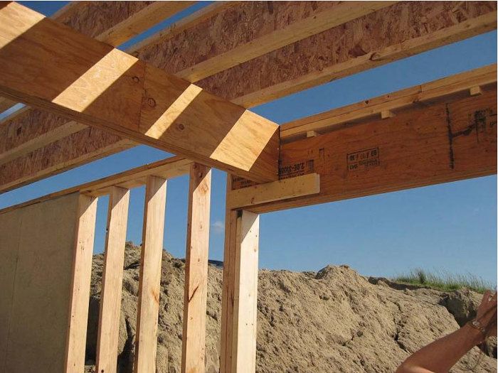
Photos supplied by canon4me show the engineered beam, one of two in the basement, toe-nailed into the header and supported by a length of 2x blocking. It will eventually get a metal hanger to make a permanent connection.
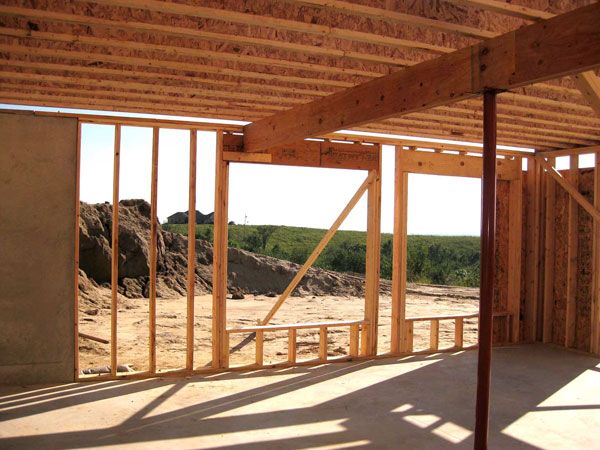
“Question is,” canon4me writes, “can this triple thick window header carry the weight of this beam...If I had known this, [I] probably would have made the windows smaller and had [the] beam supported by vertical 2x6s.”
Let the architect do the math
“I am no engineer,” writes calvin. “If the calculations are right then it will be all right.”
Ditto, says, Joe Carola. The connection will be fine, providing the architect designed it correctly, and no one but the architect can really answer that question. But assuming the architect has specified the correct hanger, this is “normal, everyday framing.”
Residential framing is relatively simple, compared with commercial work or bridges, adds k1c, and this should be a pretty simple calculation for a structural engineer. Load-bearing members don’t always have to have a direct path to the foundation, and even though the beam doesn’t land directly over a stud, it’s fairly close.
The location of the beam, he adds, “may be a compromise between the strucutral demands and your demand for big windows.”
A bigger issue, says Carola, is how a metal hanger might be attached.
He points out that the header is not tight to the bottom of the plate. Instead, it’s separated from the plate by a series of small blocks. If a face-mounted hanger is used, some of the pre-punched nail holes may fall over a void. And a top-mounted hanger should be completely supported by solid material.
“Those little nothing blocks above the header are wrong and would never carry the load of hanger, or pass inspection where I’m from anyway,” Carola says. “That’s no good. The framer made a big mistake by doing that.”
And what about the aesthetics?
The structural connection is but one issue in canon4me’s basement.
As the photo shows, the floor joists above run on top of the beam, meaning the beam will extend below the ceiling plane when it’s finished.
“The aesthetics of a dropped beam plugged into a window header might look a bit goofy,” says Scott. “Is this the look you want? And how are you going to cover them? Also think about how you are going to trim the windows.”
DanH doesn’t see a problem with the trim. From the look of it, there should be something like 6 in. between the top of the window and the bottom of the beam–plenty for window casing.
But that still leaves canon4me looking at two dropped beams in the ceiling, along with the added work of boxing them in.
“A conventional house built with conventional techniques holds few surprises, DanH adds, “and what surprises there be are easily rectified in most cases. But just scale up the house with bigger windows, longer joist spans, larger open spaces, and things get more complicated, even before you add in ‘fancy’ features like multi-story rooms, cathedral ceilings, cantilevers, glass walls, restaurant kitchens, etc.”
On that issue, k1c has one other idea:
“I thought one way to erase the beam just in that area may be to make the window area into a nook with window seats and matching drop ceiling,” he writes. “I would just double check if your corner is properly braced.”
How to fix it
OK, Carola says, the framing detail isn’t great. But it’s also easy to fix.
“All the framer has to do is take the jack studs out and move the header up tight to the bottom of the top plate and put new jack studs in,” he says. “…If the header is strong enough, the right size hanger is normal every day framing and you have no problem.”
Canon4me has another plan.
He thinks the beam should be enclosed, and supported by two jack studs and two king posts. Consequently the window will be resized and moved slightly so the beam doesn’t butt against the header at all.
“Problem solved,” he says.
Is it?
What would you do?
Fine Homebuilding Recommended Products
Fine Homebuilding receives a commission for items purchased through links on this site, including Amazon Associates and other affiliate advertising programs.

Reliable Crimp Connectors

Affordable IR Camera

Handy Heat Gun




View Comments
I would take a serious look at the feasibility of raising the header up into the floor system making it flush with the tops of the engineered joists with full bearing on the top plate of the wall. The lower header would be raised with new jack studs (as Carola says) to provide solid bearing support. This would require a longer beam and hangers for all the joists but would clean up the ceiling plane. Another drawback would be limitations on what ductwork or plumbing could be run through the ceiling cavity but should be considered as a possible solution IMHO.
Matt
The Timber Tailor
A 6" gap between the underside of the beam and the top of the window opening may technically be enough for window casing, but "enough" doesn't mean that it will look good. Details like this shouldn't get figured out during the trim stage. They should be considered at the framing stage.
I'd seriously look at moving the beam to the left of the window. There's no rule that a beam has to support the joists above in their exact centers. So long as the span is not exceeded on either side, you could move the offending beam a foot or two to the left, get it out of the header and solve the window esthetics tool
Looks to me like the architect didn't want much to do with this project and let the engineer make everything work. I hate to see time and energy expended on these kinds of details by us working class heroes when it would have been right for the architect to do his job: make a pleasing space.
The most important tool in my toolbox is an eraser. Sometimes it needs to be an ink eraser.
I agree with the TheTimberTailor, I'd see about moving it up into the floor system. You already have a column mid span so you would likely be able to get enough beam to carry the floor. If you can work out the mechanicals.
I agree with the TheTimberTailor, I'd see about moving it up into the floor system. You already have a column mid span so you would likely be able to get enough beam to carry the floor. If you can work out the mechanicals.
I agree with the TheTimberTailor, I'd see about moving it up into the floor system. You already have a column mid span so you would likely be able to get enough beam to carry the floor. If you can work out the mechanicals.
Due to the spans involved the vertical load on that header can be quite large. It looks like the members are sized correctly, but the connection is the problem. At this point the most cost effective solutions is to fabricate a custom made steel angle/plate hanger to secure the beam/header connection with through bolts.
Where to begin...I'm amazed by all of the responses that appear to have no thought towards not only the loading pattern of the beam itself, but also what the foundation conditions are below. The two pictures alone do not provide enough information to give a safe and accurate response.
The comment that suggests moving the beam over to the end of the window seems to not realize that there is already a tube column supporting one portion of the beam (possibly the middle) - thereby indicating that a pier footing is probably already centered on the column. The framer cannot simply "move the beam to the end of the window" without impacting the load path of the column - in other words, the floor slab may need to be cut out to pour a new pier footing if shifting the beam to the end of the window occurs. What about the complete opposite end of the beam? Is this already set on jack and king studs? Is there a pilaster within the opposite foundation wall to carry the point load from the jack and king studs? Is the foundation already sized large enough that it doesn't require a pilaster?
DanH. - "Normal every day framing" - hahahahah, right!
DanH. comments, "Heck, the archy/engineer coulda moved the beam to the left a foot or so without affecting the strength of the structure." From the looks of this condition, I certainly hope that a licensed architect/engineer was NOT involved with the decision to frame the beam this way. It appears to be more of a decision for a larger window after the fact the plans were already drawn - I'm guessing this was a set of plans from a house plan book and the contractor stated that enlarging the window was acceptable? Was a draftsman or designer (and not a licensed architect/engineer) used to draw up the plans and elevations that canon4me is using?
Framer comments, "The problem you have is that the framer should've put the top of the window header up against the top plates. Those little nothing blocks above the header are wrong and would never carry the load of hanger, or pass inspection where I'm from anyway." From looking at the orientation of the joists, the window header was not (originally) sized for a bearing condition but in a gable end wall and may have been sized using Advanced Framing Techniques - thus the reason why the header would not meet up to the top plates...but, the stud spacing at the load bearing wall appears not to use AFT as they don't align with the joists above. The window header as sized previously only transferred the minimal load from the non-loadbearing studs above to either side of the window. Unfortunately, the beam tying into the side of the header now makes this a bearing condition. Framer is correct though that if a top mounted hanger is used, the header (if properly sized) should have been solid up to the underside of the top plates. A face mounted hanger should not be used in this type of bearing condition due to pull-out of the nail shank.
Canon4me appears to have made a wise choice though in hiring a PE to review the entire condition. I certainly hope that monies and time wasted on reviewing this condition can be revamped by Canon4me.
Stephen F., Registered Architect
NY, NJ, PA, CT
One correction to my comment - after seeing canon4me's sketch of the exterior elevation, it appears that this is within a bearing wall after all as it carries a portion of the roof load above (as evidenced by the roof slope). Loads from the main floor and the portion of roof above would need to be considered in any loading review.
Since the house is already framed, it would be expensive to cut all of the floor joists and jack the beam to align with the bottom of the joists. The easiest solution would be to decrease the size of the window and bear the beam directly on a jack/king stud combo, yet this solution affects the alignment with the window above. The header can then be posted by a new jack/king stud combo adjacent to the header.
I would hate to see this beam in my walk-out basement though, so jacking the beam up into the ceiling space is indeed the best response aesthetically.
Stephen F., Registered Architect
NY, NJ, PA, CT
I agree with Timber Tailor... The beam should be moved into the floor system to plane with the ceiling and upper subfloor. It should also bear on a 4x Post with appropriate metal connectors at post to beam, and post to foundation (hold downs). This support post would be butted to the king stud shown at left of window opening. I just finished a job with this very detail. We were actually removing a beam that protruded into the room exactly like the one pictured. We used a large 6x18 PSL and hung the joists on it w/ hangers. Our architect and engineer provided the beam calcs. and fastening specs. Canon4me's photo shows a lame approach to framing design. The room would look like crap when done... IMHP.
Probably a case of trying to save money up front by not paying for good design/engineering, and then paying that cost plus more during construction, ultimately ending with an aesthetically unpleasing result...
Build it on paper first.
I lean towards sixthflick's take. We need to see the beam in its entirty and detail relative to the steel column i.e. poured footing.
IMHO, to heck with the windows, they are going to be a bit narrower If it was my job. Put in place proper structure at that end of the beam and the windows must lose 8" each in width. With that you clean up the placement of the window so it looks balanced between the wall and the beam, and all your window casing looks properly balanced. It seems to be the cheapest fix.
Fugly. Really Fugly. Why didn't they just raise the beam to sit on the wall and hang the joists from the beam? Way to think ahead!
Certainly the location of the beam is not in the best spot.
If the beam is in the center of the building width which appears to be ca 24' the better solution would have been to go with flat floor trusses for the whole span, eliminating the beam alltogether.
Since the framing is already in place I see the beam supported 3 inches bearing. Providing the PE has his header calculations right the hanger connection system is ok.(custom made hanger with top plate bearing). Definitely the beam should be raised to the underside of the topplates and the difference regarding windowheights adjusted on the bottom of the header.
I would also brace the bearing studs to prevent any buckling in the windowopening
When I look at the second picture, I see there are 2 windows. There is also a space between both windows which IMO looks like that is where the problem lies. Take out that gap between the windows, then this inner window moves to the right a few inches and then this problem framing is solved.
I am not sure which universe the architect dwells in but I would agree with 'otapias' that a properly designed/fabricated steel plate hanger must and should be used in this case. The support point is the foremost concern and its aesthetics are not. If the aesthetics are the factor, remove the beam and redefine the space. The critical question is the 'structural' adequacy of the support face for the beam. As an former instructor of Building Technologies and a designer of structures both residential and commercial,I would endeavor to ensure structural integrity.This is not a situation for a simple generic hanger. There are many aesthetic considerations in any structure, but in the end it is the integrity of the structure itself that rules.
regards
smalld
1. You sure could frame it flush. Where do the HVAC ducts run? Probably in a dropped chase.
2. You sure could frame it one side or another. No one here knows what the finish space is to be or exactly how the loading above is.
3. You sure could face hang it. There are many face hanger options available. Know the load - know the hanger.
4. You sure could top hang it. Infill the cripples as needed. Crushing is not an issue here and if it was you would not be top-mount hanging anyway because of the plates.
5. You sure could make the windows smaller but maybe the owner did not want that.
6. You sure could have designed the space differently.
7. So... no one here has ever framed a beam into a beam on a floor level? Guess that never works either ;-)
8. Too many what-ifs and sanctimonious not-in-my-world would that happen here speculation in this discussion.
This reads like a bunch of plan reviewers and inspectors not understanding what they are looking at.
Regards,
Charles Shade
Poor design aside there are several factors to whether this could work. The built up post under the window header is the same at both ends. This one would assume was designed for the load on the header. The load being applied to the header (from the beam) also needs vertical support. I would guess bearing area and loading on the post would be way past what this was designed for. Adding more vertical members to the post might be okay but would make the window opening smaller.
Even though the header is being loaded close to the end, we do not know (and you would not find any load tables that would address a point load like this) if it would carry the load without engineering work, that would also have to address the issue of load transfer from the beam to the header. A custom steel bracket (hanger) could be built for the beam, you CAN do almost anything, how much money do you want to spend.
I would think there would be adequate foundation in this area if the beam was designed to be in this location. Moving the beam sideways would likely require foundation work. And we do not know what the design loading and span for the floor joists are, you might not be able to move the beam. You cannot assume that you could just cut these and raise the beam either. The engineering on these joists was for them in one piece supported in the middle, cutting them changes that. If you need to know why ask an engineer. It's just not a decision the builder can make.
Bad design. An engineer should design the fix, unless you make the windows smaller and use the the original plan for the beam support. Oopps.... it's already been cut off at the inside surface of the wall, time for a decorative post to go along with featured beam!
I have agree with "Charles Shade". Everybody seems too have a valid point, but to what end if we don't have all the info. "In my opinion" I would not have designed it that way in the first place, but what do I know. There I've made my useless comment.
I respect and admire what architects and structural engineers do. However, let's not put them on too high a pedestal. Architects design buildings with aesthetics in mind and engineers decide whether or not a certain design is feasible. That is why architects' original plans are often modified. Engineers also tend to look at structural problems from an economic perspective. That is why many houses are built using two by eight joists (ie. seven and a half by one and a half), which in my opinion is inadequate. But, it does meet minimum specs. I believe in over engineering. It causes fewer problems down the road.
The design above looks like a problem waiting to happen. At least based on the information given.
@geomorph: Interesting that you feel that architects only design with aesthetics in mind. How many residential homes do you know of in which the architect hired a structural engineer as a consultant? Unless the home's structural framing is highly irregular or the loads are enormous, MANY architects design the structure themselves - why pay a consultant when you can design it yourself? Architect's original plans are often modified due to changes that were created by either clients or by contractors trying to make themselves look better to the client by changing something without the knowledge of the architect. I've been on both ends of the spectrum - as a framer and now as an architect.
Do you realize that not only are architects required to take structural courses in college, but are also required to take and pass a structural exam in order to obtain their license?
The dropped beam over the corner of the window is going to make a very awkward and unattractive detail. People have an intuitive sense of structure: columns need to look like they support the weight of what they are carrying, even if the reality is that they're a 12x12 box surrounding a 4x 4 steel tube. A dropped beam over a window will always feel like a mistake to the people in the house. They will grow to hate it and the builder who thought it would be OK.
You should cut out the portion of the beam that spans from the lally column to the wall and flush frame with hangers on the floor joists. One end can continue to be supported by the lally column. The other end can be hung from a properly sized beam and supported by whatever number of 2x columns to support it.
Check the floor joists for span capability (and being continuous over the beam helps them with that) and see if you can move that beam one foot to the jack studs and eliminate all the other trouble. Structural design was one of my focuses in my Arch. Engineering degree. But I'm a builder.
josefchalat has it completely correct. It looks just odd, and it will forever be a reminder of a basic failure in design and execution. How does one trim things out when you are faced with this visual eye sore. Just because the owner wanted those windows, in response to a previous comment, does not mean he gets them when one can explain the over all issues involved and what the end product will look like. Believe me, I have never had, seen or heard of a customer going with an extreme flub once the over all issue was explained and a reasonable solution is found.
I actually have a very similar detail in my beach house which is all windows across the front. I used 2 kings and 2 jacks as this is my place. I had a structural engineer layout the beams and hangers I am also an engineering major so I went over everything myself as a double check. I did have to fire the architect after checking his work. Yes the beams show and my wife loves them as a matter of fact. Boxing the metal hanger in wasn't too difficult and I was able to make it match the New England beach house look very well. I have photos of the rough framing and finished trim if anyone is interested. What we don't see in the photo is the other end of the beam and the detail it connects to. In my case that was a bigger factor than the window. As I said once finished it looks perfect.
Many of time I have had to "field fit" some problem that the college kids couldn't figure out. Just because you have a college degree doesn't mean jackshit! When in real life your college degree didn't allow for something this or that another. Maybe I am old school, but I don't trust sawdust or chips & glue to hold a building up. And, putting a metal hanger in a flimsy wooden wall to hold a beam that is holding the second floor up is beyond belief.
Personally, at this time in my life I just have to shake my head about what the kids will dream up next. And, if you all want, come to my house, in my back yard I am building a wooden shed from scratch, no prints, no engineering studies, no structual advice from any college kid. Only 52 years of learning experiences you'll see how a building is supposed to be built & I'm only building a shed for my a zero-turn, a chipper/grinder, a tiller & etc.
The Architect typically doesn't do the kind of math mentioned in the article. The structural engineer would normally do that. He would be in charge of checking the available strength and stiffness of the beams in question and should specify them to handle the loads without bending too much. That being said, with enough of a hanger the connection should be okay structurally. The bending moment is very low near the support and beams are nearly always overly adequate in shear, which is the main force acting against the window headder near the end of it. (This is why notching is common in framing at the ends). But the architect (if there was one) would be in charge of designing the actual space, (along with the fire resistance, egress, and waterproofing to name a few) which is certainly being compromised aesthetically by the beam being there. Unfortunately The architect can only care as much as his client's wallet allows him to. The building will only be as good as the budget and schedule allow, regardless of what grand plans were laid out beforehand. I would say the best solution, as mentioned by Tim below, would be to locate the LVL with the top flush with the joists and hang them on it. But by eliminating the overspan you will get more deflection out of your TJI's, which are bouncy as it is, so that may have required another LVL and more brackets (which are getting expensive)... or you can live with an ugly header in the basement.
It doesn't appear there is atiquite bearing on the window header. The design is poor too. The designer should have moved the beam back and reasessed the beam into the floor then hanger the joists into each side rather than spanning the joist over. Then you would get a flush ceiling.
Also it appears to be a beam to break the span, so moving it shouldn't be a problem. Any framer contractor would reassess this and go back to the architect.
1st, the exterior wall runs parallel to the joists so the exterior wall is essentially a nonload bearing wall except at the bearing point of the intersecting beam supporting the mid-span of the upper floor joists.
2nd, the adjacent window opening w/ a 2x header is way oversized. Probably no header is required at that window opening if no superimposed loads are on the 2x header from above. That way more insulation in the wall.
Now if you can reduce each window opening size what appears to be about 8-9" so the intersecting beam bears on the exterior wall header supports, you can omit the exterior LVL wall header, again, if no superimposed loads are on the header from above. If the intersecting LVL header is the same depth as the I-joists, raise the intersecting LVL so the bottom is flush with the I-joists, cut the I-joists and use simpson hangers on the LVL beam.
Finally analyze the loads at the exterior wall to see if 2x's as a post or a steel post is required for the intersecting LVL beam at the exterior wall. Be sure to infill solid blocking from the basement wall sill plate to the underside of the perimeter stud wall to provide continuous solid bearing.
raise the header and make it flush mounted.
If it was at all possible with the plan for the mechanicals I would have framed the window header top tight to the underside of the double top plates and then put the floor beam on top of the wall in plane with the joists and then hung the joists with hangers
So what was the outcome of this problem?
One conversation dominated the interval chit-chat at my most recent visit to the Globe Theatre. Everyone needs to stop
I was thinking of maybe notching the engineered beam into the triple layered header and under the header put a metal plate across from one end to the other.
Or same idea as above but lowering the window size and adding an extra header of 2X6 under triple header so that the cut notch has more bite and still adding the metal plate across.
Just thinking of ideas that's all!!!
I like wood artist awesome work
I don't know the details of the plan, maybe the beam is dropped down to allow room for ducting and pipe to run continuously through the joist spaces above, but to me the design is ridiculous.
I would move the beam up on top of the top plates, and hang the joists off of it.
One clean ceiling plane, ledger under the beam.
If you are to leave it for the aforementioned purpose, it is possible to have a steel hanger go over the top of the top plate and not rely on fasteners between the header and beam, like a big upside down J.
Otherwise, move the windows to the right or the beam to the left or the beam tot he right and get it on a ledge.
Engineers make mistakes all the time, and while this might be OK on paper, it is a silly design, and stuff happens.
Like, what if ten years from now that window has an imperfect seal, and moisture softens the OSB so it has a bit of deflection?
I wouldn't live in that house knowing what's holding the levels above me.