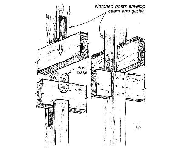
The wind can blow up to 100 miles an hour where we live on the Oregon coast, so it’s mighty important for a roof to be tied firmly to its foundation. To hold ours down, I needed a tension tie between a post, a girder, a beam, and another post upstairs. There are lots of steel brackets that can make these connections, but I don’t like looking at them. So I devised the joint shown here.
First I nailed a Simpson (www.strongtie.com) B6 post base to the top of my girder, and then I lowered it into a notch in a post sized 2 in. wider than the girder. The upper flanges of the post base tie the beam to the girder, and I notched the upstairs post to slip over the beam. This conceals the hardware and gives the appearance of a continuous post with beams passing through it. I used hardwood pegs to tie the beam and girder to the posts.
—Tom Bender, Nehalem, OR
Edited and illustrated by Charles Miller
From Fine Homebuilding #17
Fine Homebuilding Recommended Products
Fine Homebuilding receives a commission for items purchased through links on this site, including Amazon Associates and other affiliate advertising programs.

Tajima Chalk Rite Chalk Line
Sledge Hammer
Portable Wall Jack











View Comments
I don't think you want to be standing underneath that in a 100 mile hr. wind. Those notches have weakend the posts to less than a couple 2x's. And you need to look at the stats on the Simpson bracket, it's not designed to do what your attempting to do. Get an Engineer's help, or the very least, someone who knows what they're doing. That's a catastrophe looking for a time to happen!
I agree with 2morweeks. You ought to do a stress analysis on that joint for shear and tensile failure. It seems you are allowing the shear strength of the dowels to hold the joint together, but what about the tensile strength of the "legs" of your notched joint that holds the thing together, especially if you've created a notch by an errant saw cut? I suspect the bending strength lateral to the joint is compromised in orthogonal directions.
Very odd. If I understand the illustration correctly, that’s a 6x6 post with 3x8? girder. The post base would have to be nailed otherwise you would have to notch the notch to get over the Simpson hex head lag screws. Furthermore, how do the top wood pegs not hit the post flange unless they are carefully positioned where the post base flange tapers inward ? I have to agree with the above posts. It sure seems as if those outer legs of the notch might snap off like 2x4s in a Cat2 hurricane
Simpson now has a number of hidden post to beam connectors that will make this work with or without the post's flanges. Whenever it comes to lateral restraining connections leave the final number crunching up to the engineers. They went to school for that.
Just a quick reminder, this original Tip came from Issue #17...in 1983. Many of these Tips are somewhat "Out of Date". The Tom Bender I knew back in the late '70s in Oregon was an accomplished and well known architect, so this was probably as good as could be expected at the time. Take a quick look at some of his work: http://tombender.org/indexpages/designprojects.html