An Improved Stair Gauge
This jig is quicker to build than the routed-slot system, but the best part of it is the ends.

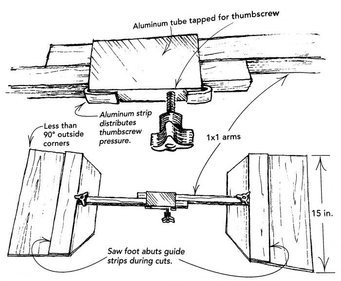
I enjoyed Bruce Abernathy’s article From Rough Frame to Finished Stairs. I use a stair gauge similar to the author’s, but I have made two important modifications. First, the length on mine is adjusted by sliding the jig’s 1×1 arms through a short piece of rectangular aluminum tubing that I tapped to receive a thumbscrew. To prevent the thumbscrew from chewing up the 1x1s over time, I slipped a thin aluminum strip inside the tube and bent the ends over so that it doesn’t fall out.
This jig is quicker to build than the routed-slot system, but the best part of it is the ends: I use short (approximately 15 in.) lengths of a standard carpenter’s door/plywood cutoff fixture, or “shooter board” (FHB #166, p. 124). I cut the ends at an angle slightly less than 90° to ensure that they will fit into out-of-square corners. To use the jig, I extend it between the stringers as in the article, but instead of having to trace the jig onto the tread, I simply clamp it to the tread and run my circular saw over it. With a standard sidewinder, the right-hand cut, as you face the front of the tread, will be made front to back. The left-hand cut, however, is back to front, so I wrap the nosing with masking tape to avoid any tearout.
This jig is easy to modify. For example, I add longer sticks to measure wall-to-wall shelves. And the sticks can be used without the cutoff ends. I typically keep a pair of 8-ft.-long sticks in the tube clamp. They are handy for obtaining awkward inside measurements, such as when I’m putting up crown molding solo.
—Harold Kirchen, Ann Arbor, MI
Edited and illustrated by Charles Miller
From Fine Homebuilding #173


View Comments
I'm not seeing the image, but the words "article image" appear at the top, with no apparent link to anything.
Makes 2 of us that can't see the image.
@jbrandeau (and FHB):
I think that this tip of mine was originally printed in FHB around 2007-8 or so, and has since cycled back through the "tipoftheday" email a few times.
At first, it was accompanied by the drawing, but the last few times FHB has only sent out the text.
The text descibes it fairly well, but as always, "a picture is worth a thousand words."
I am surprised that FHB doesn't read back through these tips to see that they have been sent out in their entirety.
If I can figure out how to contact the mods, I'll drop them a note, along with a request to send the artwork directly to you, j.
OK, Guys,
I emailed FHB about their lapse.
Unfortunately, I used their CONTACT feature without first composing a word doc on my own computer, so I have no record of the exact words that I wrote.
Anyway, if I hear back, I'll report back
Aitchkay
I like this design- using shooting boards to guide the blade eliminates one more chance to screw up...
Ref AitchKay's point about having to come at the cut from the back side and chipping the nosing, one possibility is to use asymmetrical shooting boards, a narrow one for the blade side of the saw and a wide one for the motor side. Some motors are low enough to interfere with the knob, so you might have to finesse that part of the design.
I'd be inclined to tap several holes in the aluminum tube, for when the first one strips out. Or maybe tap a strip of steel and slip it between the bent aluminum padding and the inner wall of the tubing.