FHB Logo Facebook LinkedIn Email Pinterest Twitter X Instagram Tiktok YouTube Plus Icon Close Icon Navigation Search Icon Navigation Search Icon Arrow Down Icon Video Guide Icon Article Guide Icon Modal Close Icon Guide Search Icon Skip to content
Subscribe
Log In
  • How-To
  • Design
  • Tools & Materials
  • Restoration
  • Videos
  • Blogs
  • Forum
  • Magazine
  • Members
  • FHB House
  • Podcast
Log In

Fine Homebuilding Project Guides

Framing

Guide Home
  • Introduction to Framing
  • Framing Tools, Techniques, and Materials
  • Framing Floors
  • Framing Walls
  • Framing Stairs
  • Framing Roofs
  • Efficient Framing Methods
  • Timber Framing
How-To

Installing Support Beams

Here's how to assemble and set the long built-up beams that bear the weight of the floor framing.

By Roe Osborn
  • X
  • facebook
  • linkedin
  • pinterest
  • email
  • add to favorites Log in or Sign up to save your favorite articles
Lay out a slightly oversize notch in the plate to allow for fitting the support beam, then cut out the notch.

The mudsills support the ends of the floor framing, but most houses require support for the middle of the floor framing as well. Support beams or girders provide that support. A support beam can be made of various materials, including steel, LVL, and glue-laminated 2× stock. Most often, though, it is made from built-up layers of dimensional lumber such as 2×10s or 2×12s.

Locating the support beam

The support beam for this project consists of three layers of 2×12s assembled into a beam 36 ft. long. Lally columns sit on concrete pads or footings and support the beam. The beam ends typically rest in pockets formed directly in the foundation walls. These pockets are oversize to provide an air space around the sides and ends of the beam, a detail that encourages air circulation and discourages rot. Beam pockets are deep enough to allow room under the end of the beam for a moisture-blocking pad.

Before you lay out the position of the beam, check the plans and confirm that the beam pockets are the right size and in the right places. You have some wiggle room but major discrepancies could require new beam pockets or a change in the length of floor joists.

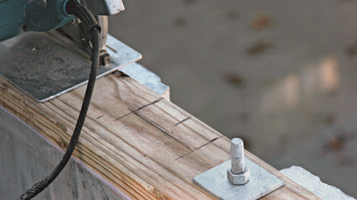
If the pockets look good, lay out the location of the beam on the mudsills. Check the plans for the distance from the front of the house to the centerline of the beam and mark this point on the mudsills at both beam pockets. Now lay out the width of the beam (4½ in. in this case) by measuring from the centerline. We also marked the location for the end of the beam because the 2×6 mudsills overlapped the beam pockets and had to be notched. The layout included a ½-in. allowance for airspace at the end of the beam.

It’s easy to figure out the thickness of the pad under the beam. Simply set a scrap of beam stock on the bottom of the pocket and measure up to the mudsills. A pad exactly this thickness will position the top of the beam flush with the top of the mudsill. Metal plates or a piece of composite decking make a good pad that won’t rot or compress.

Set a scrap of the beam material in the pocket and measure to the top of the mudsill to determine the thickness of the beam’s support pad.

Assembling the beam

Once the beam pockets are prepped, determine the exact length of the support beam by stretching a 100-ft. tape between the notches in the mudsills. Reduce this distance ¼ in. to ½ in. at each end so that the beam will slip in easily. Regular lumber doesn’t come in 36-ft. lengths, however, so you have to build the beam out of shorter boards layered together. The joints between the boards should be staggered from layer to layer so that no two joints line up at the same place. And for maximum strength, joints should fall over a Lally column.

Start building your beam by gathering the stock. Check each board for crown by sighting down one edge. The crown is any bow across the width of the board. The crowned edge should face up when the board is installed so that the weight of the building will straighten it. Mark the direction of the crown clearly as you work through a pile of lumber. Keep the straightest boards for the longest lengths; cull the worst boards to be cut into shorter lengths.

The crown is the natural widthwise bow of a board and must face up when the board is installed. Sight down each board and mark the direction of the crown.

Take the location of the support columns from the plans, and cut boards for each layer of the beam. As you cut the boards to length, make sure the ends are square. Label each board to indicate its position both by layer number and sequence in that layer.

Working from the framing plan, measure and cut individual lengths of lumber for the beam so that every joint will land over a Lally column.

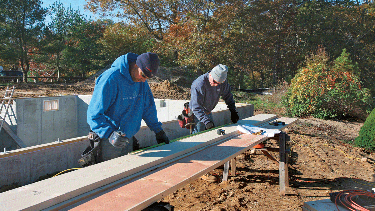
On this project, the basement slab provided a nice flat surface to work on. To assemble the beam, we arranged the first layer on the basement floor. The boards for the second layer were positioned on top of the first according to layout marks made earlier, and a quick measurement of column locations confirmed the layout. The two layers were nailed together according to the nailing schedule spelled out on the plan. The location and size of nails are details that must be followed to the letter. For this beam, four 16d nails were required every 16 in. and wherever a board bridges a seam, a row of nails must be driven on both sides of the seam.

A poured concrete basement floor offers a perfect working surface for beam assembly. Double-check every layout measurement as the labeled pieces go together.
Where a board in the beam bridges a joint in the layer below, drive a row of nails on both sides of the joint (note the joint in the middle layer).

When nailing two layers of lumber together with 16d nails, angle the nails so that they don’t go all the way through the other board. And as you nail the boards together, be sure to keep the layers flush at the top edge of the beam. Usually all that’s needed to align the edges is a hammer tap. If more force is required, drive a toenail into the misaligned board to draw the edge flush (see “Toenailing Boards Flush”).

When the third layer is nailed off according to the nailing schedule, carefully roll the beam over and nail through the back face as well, again nailing on both sides of any seam. As an added precaution against rot, nail a length of aluminum flashing around each end of the beam.

Aluminum flashing nailed to the ends of the support beam provides added protection against rot.

Toenailing Boards Flush

To align boards edge to edge, drive a toenail into the edge of the overhanging board, then pound the nail with a hammer until the board edges line up.
There are many places in house framing where two boards must be nailed together face to face with their edges flush. Unfortunately, two boards rarely have the same amount of crown and sometimes a tap of the hammer isn’t enough to make them align. In that case, drive a 16d nail at an angle through the edge of the board that must be drawn in. Then hit the nail with a hammer until the edges of the two boards line up. Drive additional nails on either side of the first if more force is needed. When the edges are flush, drive a nail into the face of the top board, near the toenails, to hold everything in place.

Setting the beam

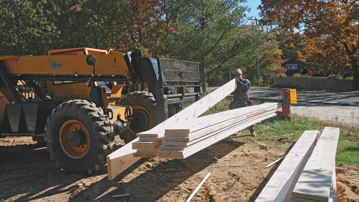
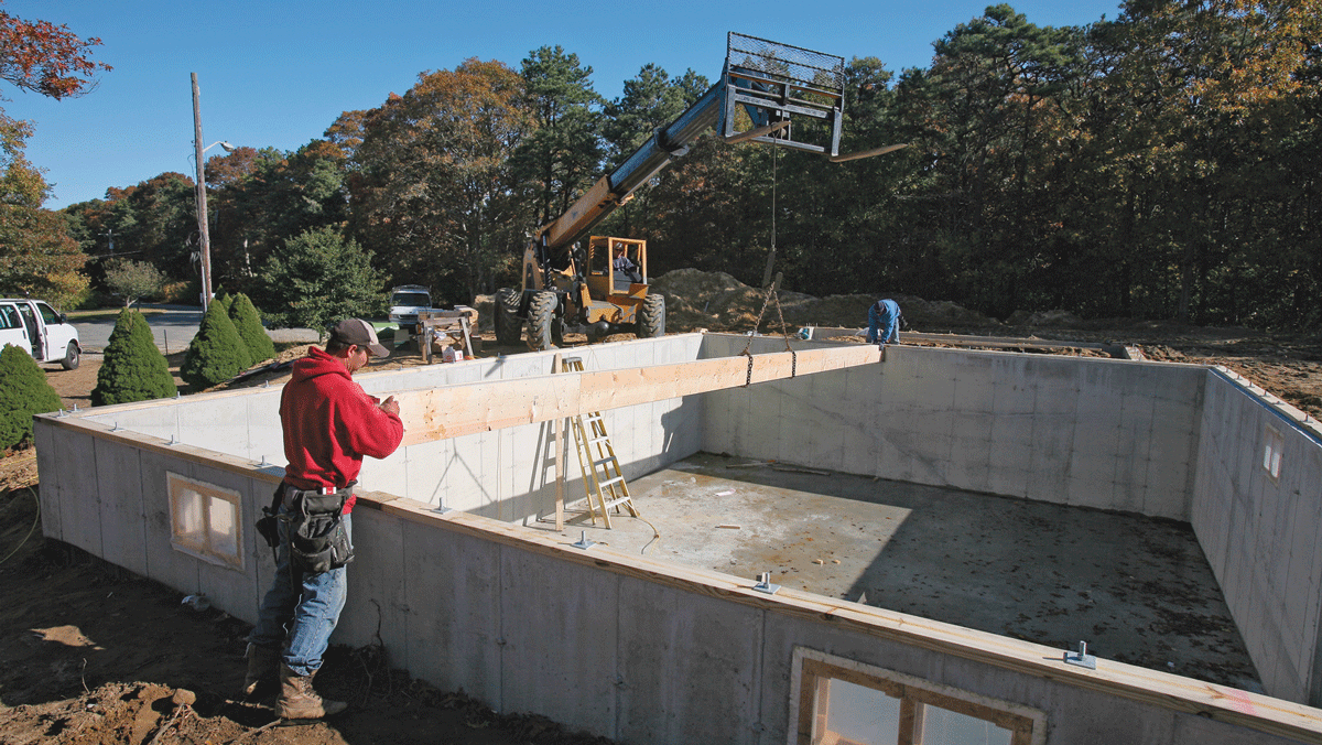
The framing contractor on this project rented a rough-terrain forklift with a telescoping boom, a machine that makes moving lumber a breeze without straining anyone’s back. More common on West Coast building sites, a lift can be rented and easily pays for itself over the course of a project. Just make sure that anyone using it has been checked out thoroughly on its safe operation.

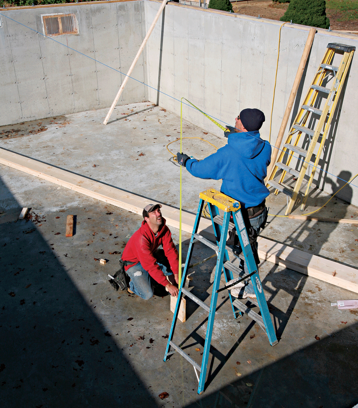
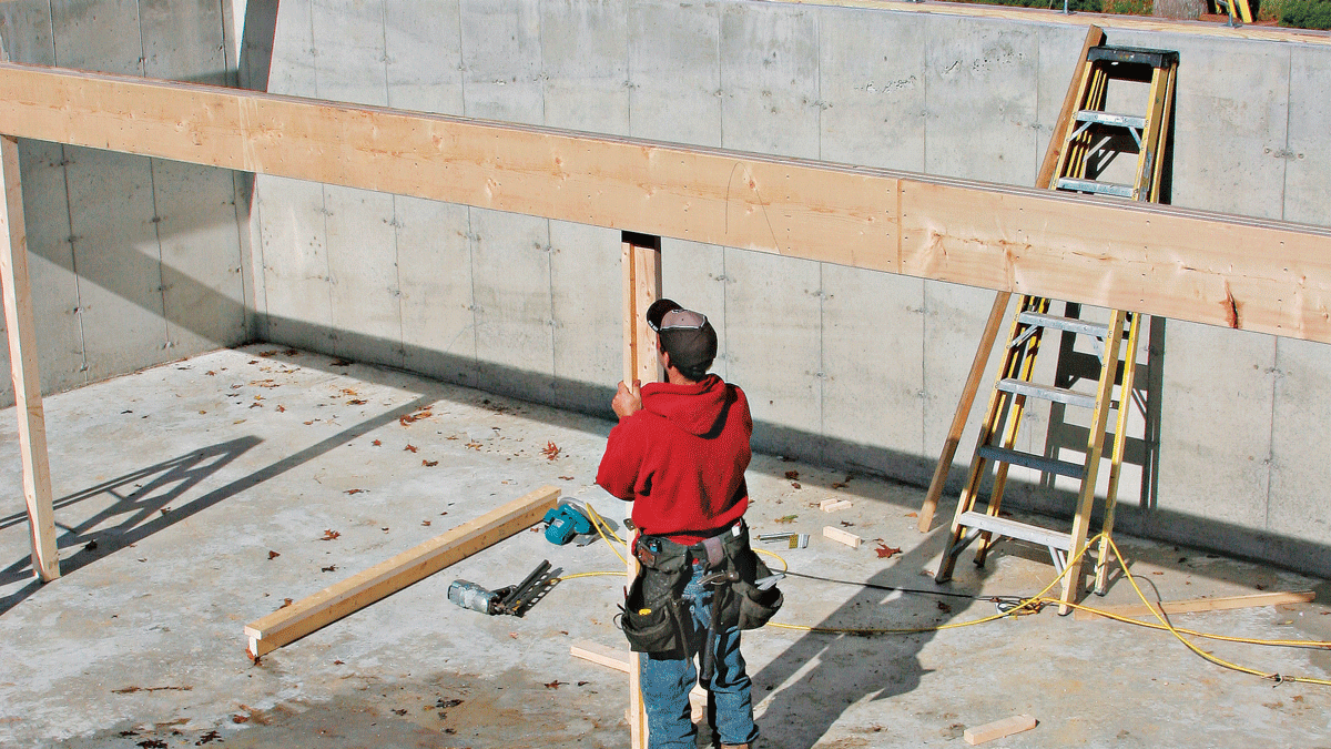
Before a beam is lifted into place, make temporary posts to support it until the Lally columns can be set. Each post is simply a pair of 2×4s nailed face to edge to increase stiffness. To determine the height of a post, stretch a string across the sills and between the beam pockets as tight as you can make it. Then at each temporary post position, set a scrap of 2×12 (the height of the beam) on the slab on edge and measure up to the string.

For the height of the temporary support posts, first stretch a taut string between the beam pockets. Then measure to the string from a scrap of beam material.
A forklift or crane makes setting the heavy support beam a safe and simple operation. Slip one end of the beam into position, then the other end.

Assembling a Beam in Place

A built-up beam can be assembled in place if it’s too long or too heavy to be lifted. Lay out, cut, and label all the pieces as described above. Starting from one beam pocket, assemble two layers of the beam and support them with adjustable A-frame trestles. Nails staggered every few feet or so are enough to hold the layers together for now. Continue assembly to the other beam pocket, placing trestles as needed for safe, solid support.

When you’ve finished the first two layers of the beam, make the entire length parallel to a mudsill and hold it in position temporarily with 2×4s nailed to the plates. Then nail the two layers together according to the nailing schedule and add the last layer (or layers), checking frequently to make sure the top edges are flush, the beam is straight, and the top of the beam is in the same plane as the top of the mudsills. Many contractors use a transit to set the height of the beam, but it’s just as easy to stretch a length of mason’s twine between the mudsills and over the beam at every Lally column position.

When assembling a beam in place, support it on temporary trestles as you work. Keep the pieces in order and be sure to follow the nailing schedule exactly. (Note the double mudsill on this project.)

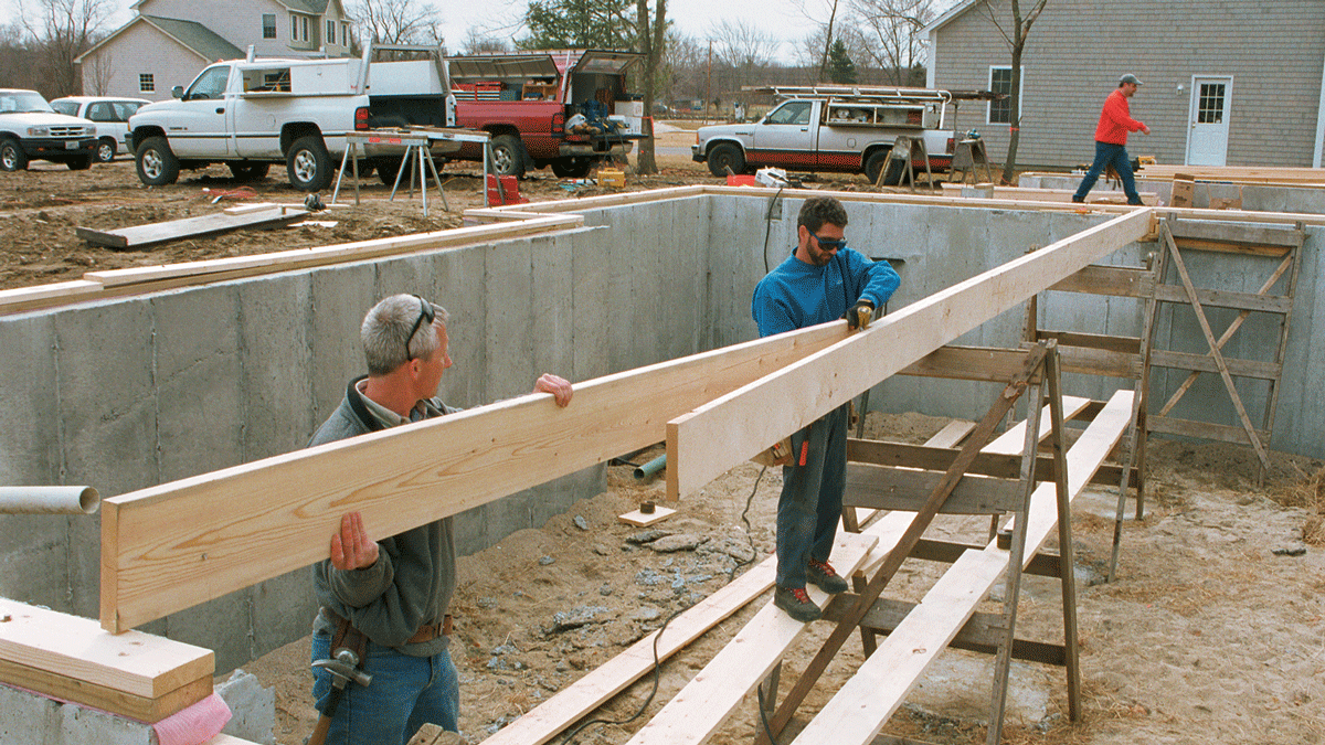
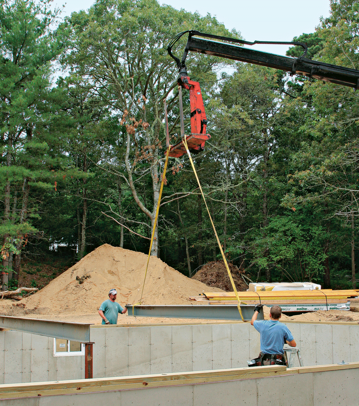
When everything is ready, roll the beam upright onto blocks and make sure the top is facing up. Next, measure and mark the exact middle of the beam. Lifting chains can then be wrapped around the beam and positioned at equal distances from the middle so that the beam is perfectly balanced as it is lifted. Once the beam clears the foundation, carefully swing it into position over the beam pockets and lower it into position. When the beam is fully seated in the pockets, set the temporary support posts in place and tack them to the underside of the beam. Be sure to set the posts where they won’t interfere with the Lally columns later on.

Temporary posts nailed in a T-shape can be tacked to the underside of the beam for support.

Steel and LVL Beams

You can minimize or sometimes even eliminate the need for Lally columns in a basement by using materials that are stronger than lumber and that come in longer lengths. A steel I-beam can often span the width of a house without the need for any columns. However, steel is costly and has to be positioned with a crane or a forklift due to its weight. A wooden plate must be secured to the top of the beam with powder-actuated fasteners to provide a nailing surface for the floor joists. Also, many municipalities require that steel I-beams be enclosed in fire-code drywall before the house can be occupied.

An LVL beam is another alternative. LVLs come in long lengths and can be bolted together to form strong beams of various dimensions, and these beams are somewhat less costly than steel. The long lengths of built-up LVLs minimize joints, but the material is much heavier than conventional lumber, and a long beam may require crane placement. The density of LVL makes hand-nailing all but impossible.

A steel beam can span greater distances than wood, but you’ll definitely need a crane to get it into place.


Fine Homebuilding Recommended Products

Fine Homebuilding receives a commission for items purchased through links on this site, including Amazon Associates and other affiliate advertising programs.

Portable Wall Jack

Raise walls safely with the Guardian wall jack — we’ve personally seen small teams raise large walls with these devices, and they work great.
Buy at Amazon

11" Nail Puller

Pulling nails is a part of framing, so this tool is always on our belts — the cats paw makes the job easy, plus the company donates to veterans.
Buy at Amazon

Stabila Extendable Plate to Plate Level

This level raises the bar for accuracy and quality. The extensions are designed to contact and plumb from bottom to top plates, avoiding studs that may be bowed.
Buy at Amazon
Previous: How to Air-Seal Mudsills Next: Installing Floor Joists

Guide

Framing

Chapter

Framing Floors

Sign up for eletters today and get the latest how-to from Fine Homebuilding, plus special offers.

Signing you up...

This site is protected by reCAPTCHA and the Google Privacy Policy and Terms of Service apply.
See all newsletters
See all newsletters

View Comments

  1. kentss | Jan 23, 2025 11:23pm | #1

    The article says, "Aluminum flashing nailed to the ends of the support beam provides added protection against rot." But the end is in contact with concrete. Doesn't aluminum flashing corrode in contact with concrete?

  2. patrick_mccombe | Jan 24, 2025 02:38pm | #2

    Hi Kent, The aluminum is more of a capillary break so the beam end doesn't absorb water moving through the concrete. Aluminum will rust when in contact with concrete but it's slow without water and a corrosive agent like salt. Peel and stick flashing tape or sill seal would perform the same job.

Log in or create an account to post a comment.

Sign up Log in

Become a member and get full access to FineHomebuilding.com

Framing

Framing

Trusted, in-depth guidance from the pros for framing a durable, code-compliant house

View Project Guide

View All Project Guides »

Become a member and get unlimited site access, including the Framing Project Guide.

Start Free Trial

Introduction to Framing
  • House Framing Concepts, Tips, and More
Framing Tools, Techniques, and Materials
  • Tools
  • Techniques
  • Framing Lumber
  • Steel
Framing Floors
  • Floor Framing
  • Engineered Floors
  • Floor Sheathing
Framing Walls
  • Wall Framing Basics
  • Layout
  • Wall Assembly
  • Raising and Straightening Walls
  • Framing Rough Openings
  • Blocking
Framing Stairs
  • Stair Layout
  • Building Stairs
Framing Roofs
  • Roof-Framing Basics
  • Roof Design
  • Laying Out and Cutting Rafters
  • Framing Valleys
  • Working with Trusses
  • Dormers
  • Special Situations
Efficient Framing Methods
  • Advanced Framing
  • Double-Stud Walls
Timber Framing
  • Timber-Frame Construction
  • Timber-Frame Design

Fine Home Building

Newsletter Sign-up

  • Fine Homebuilding

    Home building tips, offers, and expert advice in your inbox.

  • Green Building Advisor

    Building science and energy efficiency advice, plus special offers, in your inbox.

  • Old House Journal

    Repair, renovation, and restoration tips, plus special offers, in your inbox.

Signing you up...

This site is protected by reCAPTCHA and the Google Privacy Policy and Terms of Service apply.
See all newsletters

Follow

  • Fine Homebuilding

    Dig into cutting-edge approaches and decades of proven solutions with total access to our experts and tradespeople.

    Start Free Trial Now
    • Facebook
    • Instagram
    • X
    • LinkedIn
  • GBA Prime

    Get instant access to the latest developments in green building, research, and reports from the field.

    Start Free Trial Now
    • Facebook
    • YouTube
  • Old House Journal

    Learn how to restore, repair, update, and decorate your home.

    Subscribe Now
    • Facebook
    • Instagram
    • X

Membership & Magazine

  • Online Archive
  • Start Free Trial
  • Magazine Subscription
  • Magazine Renewal
  • Gift a Subscription
  • Customer Support
  • Privacy Preferences
  • About
  • Contact
  • Advertise
  • Careers
  • Terms of Use
  • Site Map
  • Do not sell or share my information
  • Privacy Policy
  • Accessibility
  • California Privacy Rights

© 2025 Active Interest Media. All rights reserved.

Fine Homebuilding receives a commission for items purchased through links on this site, including Amazon Associates and other affiliate advertising programs.

  • Home Group
  • Antique Trader
  • Arts & Crafts Homes
  • Bank Note Reporter
  • Cabin Life
  • Cuisine at Home
  • Fine Gardening
  • Fine Woodworking
  • Green Building Advisor
  • Garden Gate
  • Horticulture
  • Keep Craft Alive
  • Log Home Living
  • Military Trader/Vehicles
  • Numismatic News
  • Numismaster
  • Old Cars Weekly
  • Old House Journal
  • Period Homes
  • Popular Woodworking
  • Script
  • ShopNotes
  • Sports Collectors Digest
  • Threads
  • Timber Home Living
  • Traditional Building
  • Woodsmith
  • World Coin News
  • Writer's Digest
Active Interest Media logo
X
X
This is a dialog window which overlays the main content of the page. The modal window is a 'site map' of the most critical areas of the site. Pressing the Escape (ESC) button will close the modal and bring you back to where you were on the page.

Main Menu

  • How-To
  • Design
  • Tools & Materials
  • Video
  • Blogs
  • Forum
  • Project Guides
  • Reader Projects
  • Magazine
  • Members
  • FHB House

Podcasts

  • FHB Podcast
  • ProTalk

Webinars

  • Upcoming and On-Demand

Podcasts

  • FHB Podcast
  • ProTalk

Webinars

  • Upcoming and On-Demand

Popular Topics

  • Kitchens
  • Business
  • Bedrooms
  • Roofs
  • Architecture and Design
  • Green Building
  • Decks
  • Framing
  • Safety
  • Remodeling
  • Bathrooms
  • Windows
  • Tilework
  • Ceilings
  • HVAC

Magazine

  • Current Issue
  • Past Issues
  • Magazine Index
  • Subscribe
  • Online Archive
  • Author Guidelines

All Access

  • Member Home
  • Start Free Trial
  • Gift Membership

Online Learning

  • Courses
  • Project Guides
  • Reader Projects
  • Podcast

More

  • FHB Ambassadors
  • FHB House
  • Customer Support

Account

  • Log In
  • Join

Newsletter

Get home building tips, offers, and expert advice in your inbox

Signing you up...

This site is protected by reCAPTCHA and the Google Privacy Policy and Terms of Service apply.
See all newsletters
See all newsletters

Follow

  • X
  • YouTube
  • instagram
  • facebook
  • pinterest
  • Tiktok

Join All Access

Become a member and get instant access to thousands of videos, how-tos, tool reviews, and design features.

Start Your Free Trial

Subscribe

FHB Magazine

Start your subscription today and save up to 81%

Subscribe

You have 1 free article remaining.

Get complete site access, including thousands of videos, how-to tips, tool reviews, and design features.

Start your FREE trial

Already a member? Log in

We hope you’ve enjoyed your free articles. To keep reading, become a member today.

Get complete site access to expert advice, how-to videos, Code Check, and more, plus the print magazine.

Start your FREE trial

Already a member? Log in

Privacy Policy Update

We use cookies, pixels, script and other tracking technologies to analyze and improve our service, to improve and personalize content, and for advertising to you. We also share information about your use of our site with third-party social media, advertising and analytics partners. You can view our Privacy Policy here and our Terms of Use here.

Cookies

Analytics

These cookies help us track site metrics to improve our sites and provide a better user experience.

Advertising/Social Media

These cookies are used to serve advertisements aligned with your interests.

Essential

These cookies are required to provide basic functions like page navigation and access to secure areas of the website.

Delete My Data

Delete all cookies and associated data