Critical Details for Ductless Heat Pumps
Trouble-free performance begins with properly installed line sets that pass rigorous testing for leaks.
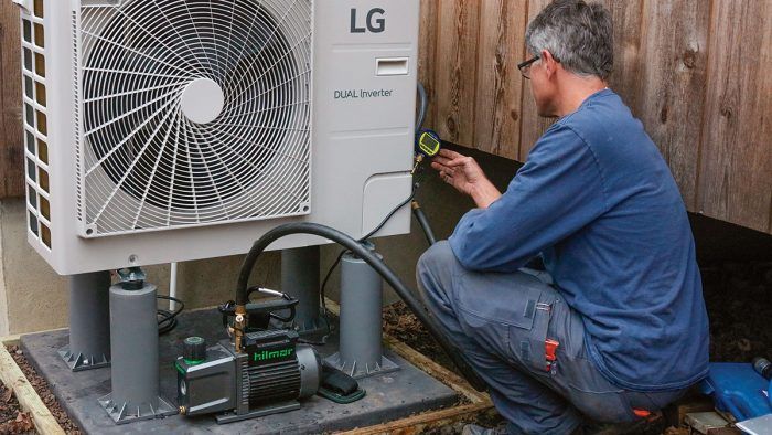
Synopsis: HVAC project manager Jon Harrod describes the surge in popularity for ductless heat pumps, sometimes referred to as minisplits. He describes the main causes of heat pump failure; including refrigerant and condensate leaks, defrost problems, clogged filters, and temperature issues, how to ensure a good installation, and the importance of educating customers about common pitfalls.
Ductless heat pumps are surging in popularity. This growth has been driven in part by improvements in technology that allow them to perform well in cold climates. Recent increases in fossil fuel prices have also contributed, as have state and utility programs that aim to reduce carbon emissions by electrifying buildings. The recently enacted Inflation Reduction Act will further boost heat pump adoption by increasing federal tax credits and funding new rebates.
The boom in ductless heat pumps is bringing new installers to the field. Some come from traditional HVAC backgrounds and are more familiar with conventional furnaces, boilers, and air conditioners. Others—electricians, home-performance contractors, carpenters—come from related trades; some are new to contracting.
The barriers to becoming a ductless heat pump installer are relatively low in terms of basic skills and required tools. But despite their seeming simplicity, ductless heat pumps can be unforgiving of poor design and workmanship. A bad ductless installation can become a nightmare for homeowners and contractors alike. And bad outcomes lead to bad publicity, slowing heat pump adoption.
A few easily avoided errors are responsible for most problems I’ve seen on ductless systems. If you’re a contractor, paying attention to these critical details can avoid costly callbacks. If you’re a homeowner, knowing about these pitfalls can help ensure your new system is trouble-free.
Proper installation means a leak-free refrigerant circuit
Heat pumps work by moving heat between the indoors and the outdoors. The fluid that carries the heat is known as a refrigerant. As refrigerant moves through the system, its pressure is raised and lowered, and it changes back and forth between gas and liquid states. As it enters the warm side of the system, the refrigerant is compressed, raising its temperature. In heating mode, this hot, high-pressure gas condenses in the indoor coil, transferring heat to the house air. As the refrigerant, now a warm liquid, returns from the indoor coil, it passes through a metering device, and its temperature and pressure drop. The refrigerant evaporates at the lower pressure, absorbing heat from the cold outdoor air. In summer, the process is reversed; the indoor coil becomes the heat-absorbing evaporator, and hot, high-pressure refrigerant condenses in the outdoor coil, releasing heat.
Ductless heat pumps are sometimes referred to as “minisplits.” Both ducted and ductless heat pumps are “split” systems; their indoor and outdoor coils are in separate pieces of equipment. Rather than distributing conditioned air through ductwork, ductless heat pumps use freestanding heads mounted on walls or ceilings that blow directly into the spaces they serve. “Minisplits” refers to the smaller Btu outputs available in ductless units (as small as 6000 Btu, versus 18,000 to 60,000 Btu for most ducted systems). Here I focus on ductless heat pumps, but many of the same concerns also apply to ducted systems.
Crucial connections
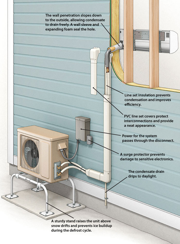
A successful ductless heat pump installation requires attention to the placement of indoor and outdoor units and to the interconnections between them. Placement considerations include visual and sound impacts, airflow, protection from damage, and minimum and maximum allowable line set lengths. Refrigerant lines must be leak-free and fully insulated. Power circuits and communication cables must be sized and installed in accordance with the National Electrical Code and the manufacturer’s instructions. Condensate piping must be correctly pitched with no traps or upward slopes and must not terminate in soil or mulch. All system components must be properly supported.
To function properly, the refrigerant circuit needs to be leak-free. A system that is slightly low on refrigerant will run inefficiently and struggle to achieve its rated output. A system that is very low will likely shut down entirely. Running with low refrigerant puts extra wear and tear on critical components like the compressor. And, because refrigerants like the R-410A used in modern heat pumps are potent greenhouse gases, leaks are a major environmental concern.
A heat pump’s indoor and outdoor units are connected with copper tubing called line sets. In ductless systems, the connections are usually made with flare fittings. A well-made flare can provide a durable, leak-free connection. Flaring remains the most common technique for connecting ductless line sets, but other approaches are available. Brazing (a process similar to soldering copper plumbing) is widely used for conventional heat pumps and air conditioners and can also be used for ductless systems. Crimped and push-to-connect fittings are also becoming popular. If these alternative fittings are used, follow manufacturer instructions carefully. Regardless of the connection type, a thorough leak check should be performed before refrigerant is added. No single test can detect all leaks, but a four-step methodology can catch all large leaks and most smaller ones.
Condensate leaks can be prevented
In the summer, heat pumps cool and dehumidify indoor air. As the air passing over the indoor coil cools to its dew point, moisture condenses and drips into the drain pan below. In a typical ductless installation, a flexible hose carrying the condensate exits through the rear of the indoor unit and passes through the exterior wall. The hose connects to a drainpipe. The drainpipe carries the condensate down to the bottom of the wall, where it drips onto the ground.
If the pan, hose, or drainpipe are blocked or incorrectly sloped, the condensate will back up, usually running down the wall behind the indoor unit. There are some key takeaways when it comes to preventing condensate leaks during installation. The first is to mount the indoor unit level or sloped slightly toward the opening on the drain pan. When drilling the hole through the wall for the condensate drain, drill so that it pitches toward the exterior, and make sure that the flexible drain hose slopes downward as it exits the wall. To keep the hose in the correct position, tape it below the stubs for the refrigerant tubing before feeding the whole bundle through the wall. Exterior condensate drains should be made of rigid or semirigid materials like PEX or PVC. Check that all hose and pipe connections are properly clamped and ensure that the exterior drain slopes downward continuously with a minimum pitch of 1 ⁄ 4 in. per ft. Secure it at regular intervals to prevent movement or sagging. Terminate the bottom end of the drainpipe above grade—don’t submerge it in a puddle or bury it in soil or mulch.
Test condensate drains on every install. With the system off, pour a couple quarts of water slowly over the coil. Condensation can also form on poorly insulated line sets running through conditioned and unconditioned spaces. Thorough line set insulation is worthwhile as an efficiency measure, but its biggest benefit is preventing condensate drips.
Condensate problems tend to show up all at once during the first hot, humid week of summer. Once the system is installed, regular maintenance, including cleaning drain pans and piping, is critical for preventing condensate leaks.
Defrost problems develop in cold temperatures
To absorb heat in winter, a heat pump must make its outdoor coil colder than the air passing over it. When outdoor temperatures are below 40°F, coil temperatures drop below freezing, and frost builds up. Too much frost blocks airflow through the coil and prevents the heat pump from operating efficiently. To clear this frost, heat pumps must periodically go through a defrost cycle. The system stops heating and temporarily reverses refrigerant flow, taking heat from the house and using it to warm the outdoor coil. The outdoor fan shuts off to speed the melting process. To minimize comfort issues, ductless units typically turn their indoor fan to low speed and adjust their louvers to direct the cool air up and away from occupants.
A few simple steps can prevent many defrost-related callbacks. First, educate homeowners about the defrost cycle, which is a normal and necessary part of cold-weather operation. Letting homeowners know that the system will periodically stop heating and gently blow cool air can avoid complaints like “This thing has a mind of its own!”
It’s also important to protect outdoor units from bulk water. Concentrated snowmelt or heavy rain falling on the outdoor unit can lead to excessive ice buildup on the outdoor coil. When possible, locate outdoor units away from drip lines and roof valleys. Where heavy snow or runoff is a concern, consider a protective roof or awning. Elevating outdoor units above snow depth is important for their operation in northern climates. Elevating the unit also allows meltwater from the defrost cycle to drain away freely. Be careful of placing outdoor units near walkways, where meltwater can refreeze and create a slipping hazard.
In colder climates, use a drain-pan heater, which is a small electric-resistance coil that prevents water melted during defrost from refreezing inside the outdoor unit. Without this heater, ice can build up, eventually blocking and damaging the coil. Many heat pumps designed for cold-climate use come with drain-pan heaters already installed.
Three steps to making a flare fitting
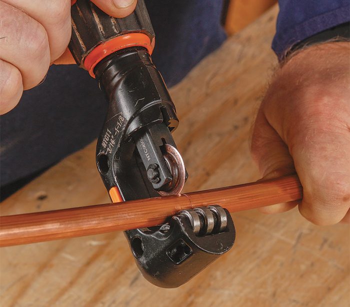
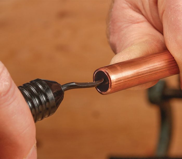
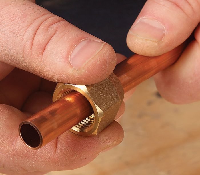
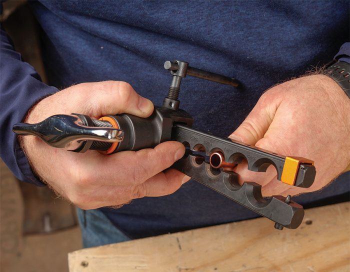
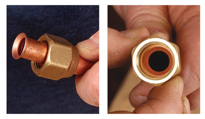
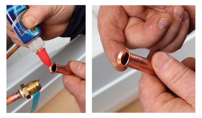
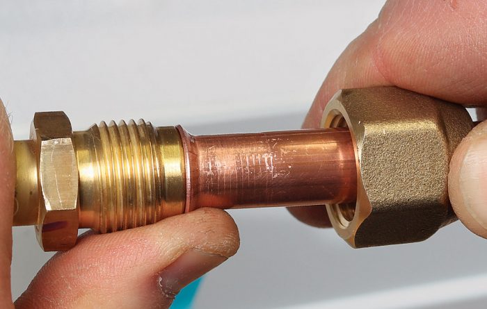
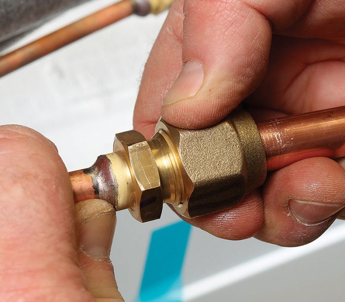
In ductless heat pump systems, the indoor and outdoor units are connected with copper line sets and flare fittings. A well made flare is essential to a durable, leak-free connection.
Step one: Prep the tubing
Step two: Forge the flare
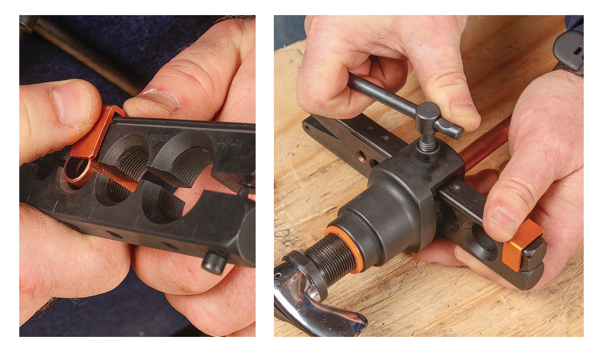
Step three: Connect the fitting
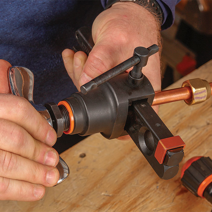
Temperature issues are the trickiest
Of the common problems with ductless installations, those involving temperature control are among the hardest to resolve. I will touch on a few common issues here. The following guidance assumes that you’ve fixed any glaring defects involving insulation and air leakage and performed accurate heating and cooling load calculations; these steps are critical to delivering good results with any system type.
One issue involves a mismatch between the set point on the ductless controller and the temperature measured in the living space. This problem is inherent in the design of ductless systems. The indoor temperature sensor is mounted on the ductless head itself. For high-wall ductless heads, this means that the sensor is usually 6 ft. or 7 ft. off the ground. The tendency of warm air to rise and the sensor’s proximity to the warm indoor coil mean that the temperature it senses is often a few degrees warmer than that experienced by occupants lower in the room. One way to mitigate this issue is by mounting ductless heads at least 6 in. to 8 in. below the ceiling to reduce the effects of temperature stratification. This also allows the head to draw in slightly cooler air, improving the efficiency of heat transfer. Using medium to high fan speeds can also reduce temperature stratification and provide better mixing in the room. Another solution is a remote thermostat, which allows the ductless head to sense temperature closer to occupant level.
Regardless of which solutions are employed, it’s important to educate homeowners about ductless temperature sensing. I encourage homeowners to choose a set point at which they’re comfortable, even if it’s a few degrees higher than they have set their thermostats in the past.
Another temperature-related issue is specific to multizone ductless systems. In these systems, multiple indoor heads connect to a single outdoor unit. A typical example might involve an outdoor unit connected to a larger head in the living room and smaller heads in three bedrooms. Problems arise when only one of the smaller zones calls for heat. The outdoor unit can ramp down its output, but only so far; most multizone outdoor units can modulate down to about one-third their maximum capacity. If the head calling for heat can’t handle the outdoor unit’s minimum output, the system may bleed refrigerant through the other heads, causing unwanted heating or cooling in those zones. It may also cycle on and off, leading to extra noise, efficiency loss, and wear on the system.
One way to avoid this issue is by using multiple single-zone heat pumps (“one-to-ones”) rather than a multizone system. Single-zone heat pumps can typically modulate down much lower than multizone systems. The issue can also be solved by using a ducted air handler to serve a group of rooms. For example, if a three-bedroom house has all the bedrooms in the same general area, they could share a compact air handler rather than each having its own head. The air handler, providing heating and cooling for all the bedrooms, can better handle the outdoor unit’s minimum output.
Other issues with poorly designed multizone systems include efficiency losses and noise. Though it’s tempting to design whole-house solutions around multizone outdoor units, I always make a point of considering other options.
Four tests to prevent refrigerant leakage
Refrigerant leaks are one of the most common causes of callbacks for ductless heat pump systems. They can present in various ways: as complaints of inadequate heating or cooling, as error codes and intermittent lockouts, as iced-up indoor or outdoor coils, and as high energy bills. Left unaddressed, refrigerant leaks can significantly reduce equipment lifespan. They are also a serious environmental issue; common refrigerants have global warming potentials thousands of times greater than CO2. There are four tests that installers can use to ensure that refrigerant piping is tight before refrigerant is added to a potentially leaky system. Each of these tests has its strengths and limitations; the four, taken together, will catch almost all large leaks and many small ones.
The extra time thorough testing adds to an installation will be more than made up by avoided callbacks. General contractors, project managers, and consumers involved in heat pump projects should insist on these tests—and on documentation of passing results—to make sure that the work meets their standards for comfort, durability, and environmental stewardship.
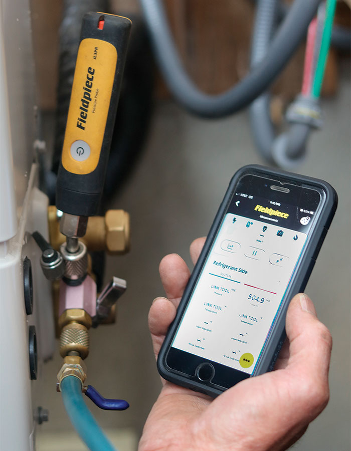
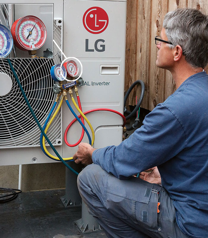
1. The Standing Pressure test involves filling the line sets with high-pressure nitrogen. This test is good at catching large leaks, but its sensitivity is limited by the duration of the test (usually 45 minutes to 24 hours), pressure fluctuations caused by changing outdoor temperatures, and the resolution of gauges. Shown here is an analog pressure gauge, which can be read to within about 1 psi.
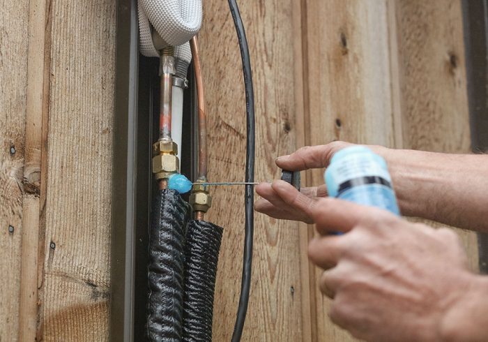
2. The Bubble test is done while the system is under pressure, and is more sensitive to small leaks than the standing pressure test. For the bubble test, an approved leak-testing solution is sprayed or dabbed on the flares. If after about 10 minutes bubbles form, this means a leak is present and the flare must be re-done.
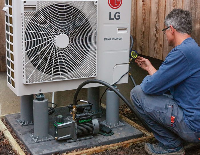
3. The Vacuum Decay test is done just before filling the line sets with refrigerant. At this point, the line sets have been pumped down into a deep vacuum to remove air and moisture. The vacuum level is measured with a sensitive micron gauge. To pass this test, the system must hold the deep vacuum after the pump is turned off.
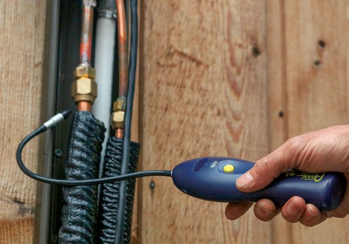
4. The final test is done with an Electronic Refrigerant Leak Detector. Once the refrigerant is released into the system, the leak detector is passed over flares and other fittings. This provides a last chance to catch leaks while still on-site. It also checks components like service valves and access ports that cannot be tested by other methods.
Sophisticated electronics need surge protection
Modern cold-climate heat pumps are packed with sophisticated electronics. Their boards contain power-control circuits that change alternating current into variable-frequency direct-current signals, allowing compressors to speed up or slow down in response to heating or cooling demand. Sensors and microprocessors also coordinate the operation of the compressor, indoor and outdoor fans, and refrigerant metering valves, optimizing the system across a wide range of indoor and outdoor conditions.
These microprocessors and circuit boards, so critical to the operation of cold-climate heat pumps, are also their Achilles heel. The electronics can be damaged or destroyed by power surges, either in a single catastrophic event or gradually through a series of lower-level surges. The damage can render a system inoperable. A fried circuit board can’t be repaired; it needs to be replaced.
Fortunately, it’s easy and inexpensive to add surge protection to a heat pump system. Surge protectors work by shunting current away from the appliance and into the ground. HVAC surge protectors are typically installed on the outdoor disconnect. With the power to the circuit shut off at the panel, the disconnect is opened up, and a knockout is removed from the bottom or side. The surge protector’s wires and a threaded nipple are fed through the knockout, and the device is secured with a locknut. The two black wires are connected to the incoming line wires, and the green wire is connected to the ground wire. The disconnect is closed up and the circuit re-energized. The entire process takes less than 15 minutes.
While adding surge protection as part of new installation does add a modest upfront cost, it can prevent much larger headaches down the road. And once installed, surge protectors are essentially maintenance-free. Homeowners should be instructed to monitor the indicator LED to make sure the device is still active and to call for replacement should the LED go out. Service techs should also check surge protectors as part of preventive maintenance. To avoid damage to equipment, worn-out surge protectors should be replaced promptly.
Dirty filters are easily cleaned
A common but easily resolved ductless callback is caused by clogged filters. This usually shows up as a complaint of insufficient heating or cooling. One of the ways that ductless systems achieve their high efficiency ratings is by minimizing fan energy. The drawback of lowpowered fans is that they can’t overcome much resistance to airflow. Ductless filters are made of a coarse plastic mesh. When clean, they allow air to flow freely. But they can easily become clogged with pet hair, cobwebs, and other household dust. And without good flow across the indoor coil, the ductless head loses its ability to heat and cool.
Cleaning a ductless filter takes about 10 minutes. I prefer a handheld vacuum with a small brush attachment. How often a filter requires cleaning depends on dust load and especially the number and size of shedding pets. In some homes, filters need cleaning every two or three weeks; in others, every two months is sufficient.
To ensure that customers keep their filters clean between our annual service visits, we need better customer education. It’s important to carve out the time to take customers through operation and maintenance step by step. Don’t tell them they need to clean their filters; give them a hands-on demonstration.
Careful attention goes a long way
As we look to scale up ductless heat pump installations, callback prevention is key. Callbacks are costly and discouraging for contractors and upsetting for homeowners. There’s a lot of information to absorb, so I like to leave customers with a one-page guide that covers key points, including best practices for operation, filter cleaning, annual service, and warranty coverage. With customer education, as well as careful attention to key details of system design and installation, some of the most common callbacks can be avoided.
—Jon Harrod is a writer, HVAC project manager, and building science consultant based in Ithaca, N.Y.
Photos by Rodney Diaz.
From Fine Homebuilding #314
RELATED STORIES


View Comments
I have installed 14 single mini split units. Even though I pressure tested with dry nitrogen at 400 to 500 PSI (depending on manufacture instructions) two units leaked later at the flare fittings, so I started using Rectorseal Flaring seals. (Maybe if I use the torque wrench at the flare fitting I would not have his problem)
Mitsubishi (and others) specify, a triple evacuation during installation. That’s where you pressurize the system with dry nitrogen, release the nitrogen attach the vacuum pump for about an hour, then repeat the process two more times. The exact pressures are in the installation instructions.(leak check when pressurized with nitrogen)