Post and Beam Layout on a Small Freestanding Deck
Learn how to build a long-lasting, resilient deck frame starting with post-base connections, posts, and beams.
Sponsored by Trex®
Mike Guertin prefers building freestanding decks because they eliminate the need for flashing against the house, and in most code jurisdictions, footings for freestanding decks only need to be one foot below excavated soil, rather than reaching frost depth. In this video, Mike shares several crucial skills for building an attractive, long-lasting deck using Trex® products.

Here’s the Transcript:
I like a freestanding deck, and most of the decks I build are freestanding, primarily because I don’t have to do any flashing work up against the house. Also, in most code jurisdictions, the deck footings themselves do not have to go to frost depth. You only need to be 1 foot below any excavated soil.
Several months ago I ganged together the deck boards to get dimensions for the deck design, but I wanted to double-check it now. We’re installing Trex® Hideaway Fasteners, just dry fit. I’m using a system where the hidden fasteners are designed and intended for use with the decking we’re installing, so it all works as part of a system. We’re dry-fitting these to get the dimension from the house side of the deck to the outside face.
I ganged together the hidden fasteners and needed two dimensions. One is the dimension of two deck boards plus the airspace, which adds up to just under 11½ in. This will be the size of the two steps leading up to the top of the deck frame. The second dimension is from the house side of the deck boards out to the front.
Now we’re targeting roughly 5 feet for our deck, so I could do one of two things. I could dial it back and go with 57 in. for our finished deck depth from the inside of the house to the outside edge of the nosing of that last border board, or I could bump it up to 62-¾ in. I talked with the homeowner about this, and we’re going to go a bit over 5 feet, so we’re setting the final dimension at 62-¾ in.
From that measurement, now I can design the deck frame. I’m going to subtract an airspace at the back of the deck. And I’m going to subtract the nosing, the fascia board, and a little bit of an airspace behind the fascia board to the deck frame. Once I subtract those, I’ll have the deck-frame dimension.
What to Do After Deck Dimensions Are Locked In
Now that we have our deck dimensions, we’re going to figure out where the anchor is going to go. We marked out the story pole to match the center positions for all of our important points that were on the plans. So now we can snap the lines.
We snapped the chalklines to be the back of the framing that’s going to support the deck stairs. I want to use a 2x to gauge the distance between the bin and the face of the concrete, because any portion of the concrete beyond the face of my tie will need to be trimmed off with a grinder. You can see here that this whole portion of the footing will have to be chopped back; otherwise, it will interfere with the homeowner’s concrete paver patio that’ll be installed later.
Anchors Away
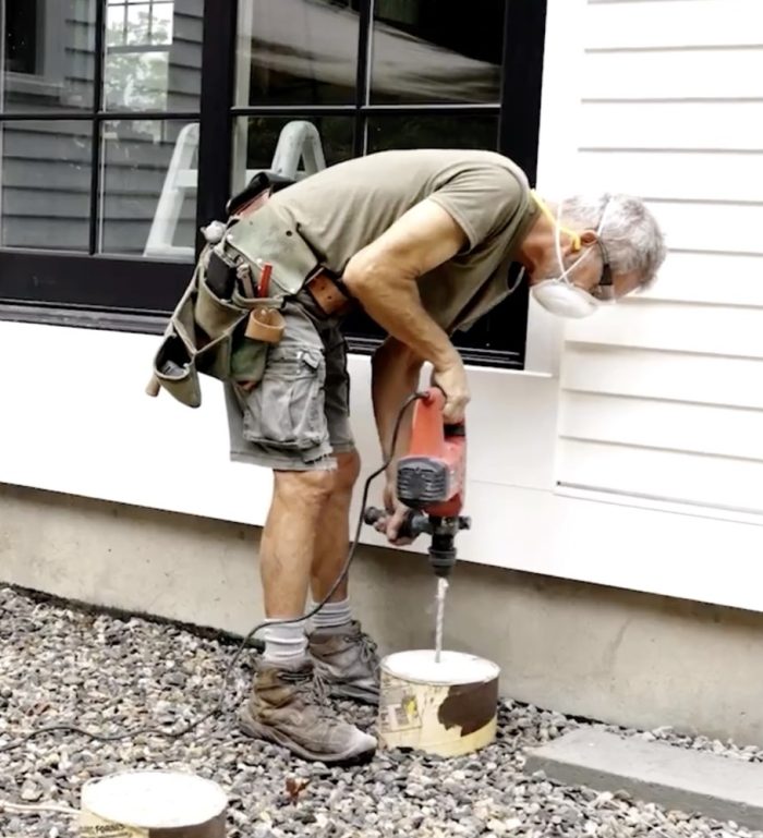
Instead of putting the anchors in during the pour, when the concrete is still plastic, I like to drill the hole afterward because that gives us much more control over precisely locating that hole. The reason I blow out the holes is to keep the dust stuck on the side of the shaft from gumming up the bolt when it goes down into the hole.
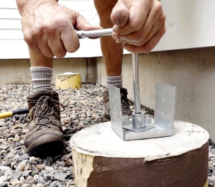
This is a post base, and we need to anchor it to the footing. We’re using expansion anchors (wedge anchors), which have a little collar on them and a flared bottom. When we drop this in, it goes in like a fish hook. When we draw it out, as we turn the nut, that collar will expand, pressing against the side of the hole, and hold that fast to the footing.
Post-Height Adjustments
We got the post bases in, and the next thing we have to figure out is the height of the posts. I made a story pole that references all the important points on the whole deck in vertical planes: patio, finished top of the frame for the first step, top of the frame for the second step, top of the deck framing, and the top of the door threshold, which is where we established a height for all the tops of the deck. This way, when you step from inside the house down to the deck, it won’t be too tall. Then we mark the bottom of the beam, which is going to be the top of the post.
What we’re going to have Addison do now is set the height of the laser receiver so that it registers to our reference point. He can just draw right across here onto our post. That way we don’t have to do any measuring and marking—we’re doing it in one step. This method gives us a lot more accuracy, going direct from the story pole right to the post. That line is going to be the top of the post, which is analogous to the bottom of the beam.
Placing Posts
We’re ready to start putting the posts in, but before we can do that, we have to coat all of the cut ends of the posts, as well as all of the joists and beams later on, with copper naphthenate. This has been a code requirement for at least the last 20 years, and you’re supposed to coat it until it accepts no more of the solution. It could be one brush over, or it could be two, three, or four. We usually put it on and then let it sit.
Build Longer-Lasting Decks
We could just put the post in and nail it in place. The coating is good enough to be in contact with the pressure-treated lumber. But an extra step you can take to improve the longevity of the hardware is to put an isolation membrane between the pressure-treated lumber and the metal hardware.
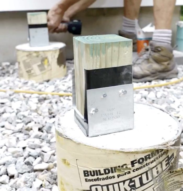
This includes the post base, post caps, joist hangers, and tie-down clips—anywhere you have metal hardware touching the pressure-treated lumber. The isolation membrane I’m using is nothing more than the flashing tape that Trex® has for putting over the tops of joists and beams (Trex® Protect Joist, Beam, and Rim Tape). This is their 4-in. tape.
We got the beams cut to length; they’re the same length as the deck that the joists will rest on, and I’ve got to nail them together. There’s a pattern that the code dictates. We need a row across the top and a row across the bottom, 16 in. on center, and they should be staggered. We’re going to do an up-and-down pattern offset by 8 in. We’ll use a minimum of a 3-in. long galvanized nail.
We use nails to attach the post bases, and we’re using connector screws to attach the post caps. They are interchangeable and work fine. I’m using another piece of Trex® Flashing Tape as an isolation membrane. Because it’s hard to position the tape on the beam, as we’ll be shifting it back and forth, I’m applying the tape to the hardware first. It’s not as easy to apply it to the hardware first, but it makes more sense in this instance.
What I’m doing here is using 1-in. blocks as spacers. All of our deck framing will be spaced 1 in. off of this skirtboard. We have spacers to space the beam, joists, and rim board on the inside. This way, water can flow through if it gets underneath the decking.
This is the Trex® Protect Beam Tape. They also have joist tape, which is about 1-⅝ in. This is about 3-⅛ in. and is made to cap over the top of a double 2x beam. The reason we put the flashing tape on top of the joists and beams is to extend the life of the deck.
You don’t think about pressure-treated wood as being vulnerable to decay, but it is. The more we can keep water from getting into the middle of the wood, the longer it’s going to last. This deck could last 50 or more years easily with these extra steps we’re taking.
RELATED STORIES


