
Roughing-in Drain-Waste-Vent Pipes
Renovation expert Mike Litchfield explains 3 ways to tie into an existing soil stack or drain.
In new construction, pros typically start the drain-waste-vent (DWV) system by connecting to the sewer lead pipe, supporting the main drain assembly every 4 ft. and at each point a fitting is added.
Renovation plumbing is a different matter altogether, unless an existing main is so corroded or undersize that you need to tear it out and replace it. Rather, renovation plumbing usually entails tying into an existing stack or drain in the most cost- and time-effective manner. There are three plausible scenarios: (1) cutting into a stack to add a branch drain, (2) building out from the end of the main drain where it meets the base of the soil stack, and (3) cutting into the main drain in midrun and adding fittings for incoming branch drains.
This discussion assumes that the existing pipes are cast iron and that new DWV pipes or fittings are ABS or PVC plastic, unless otherwise noted. If you’re adding several fixtures, position the new branch drain so that individual drains can be attached economically—that is, using the least amount of pipe and fewest fittings. Remember, drainpipes must have a minimum downward slope of 1⁄4 in. per ft.
Run clear water through the drains before cutting into them. Flush the toilets several times and run water in the fixtures for several minutes. Then shut off the supply-pipe water and post signs around the house so people don’t use the fixtures while work is in progress.
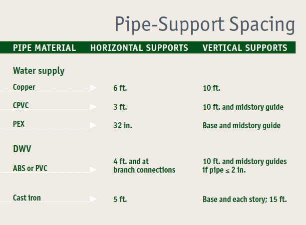
Going with the FlowTo optimize flow and minimize clogged pipes, follow these guidelines:
|
Splicing a branch drain into a stack
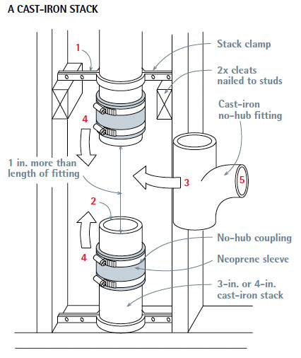
If you’re adding a toilet, have a plumber calculate the increased flow, size the pipes, recommend fittings, and—perhaps—do the work. Adding a lav, sink, or tub, on the other hand, is considerably easier and less risky—mostly a matter of splicing a 11⁄2-in. branch drain to a 2-in. or 3-in. stack. The basic steps are clamping the stack before cutting it, inserting a tee fitting into the stack, and joining the branch drain to that fitting.
Let’s look at splicing to a cast-iron stack first. Start by holding a no-hub fitting (say, a 2 by 1 1⁄2 sanitary tee) next to the stack and using a grease pencil to transfer the fitting’s length to the stack—plus 1⁄2 in. working room on each end. (This gap at each end will be filled by a lip inside the neoprene sleeve.) Install a stack clamp above and below the proposed cuts. Then use a snap cutter to make the two cuts. Drill through studs as needed to run the branch drain. Next, slide no-hub couplings onto both cut pipe ends; in most cases, it’s easiest to loosen the couplings, remove the neoprene sleeves, roll a sleeve halfway onto each pipe end, and then replace the couplings.
 |
 |
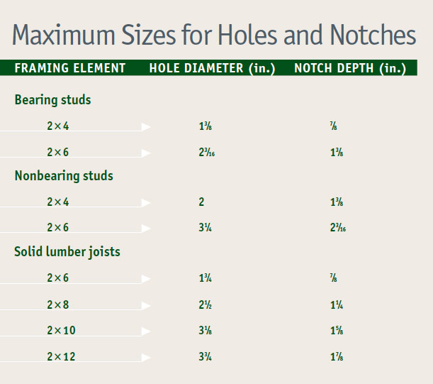
Drilling and Notching Studs and Joists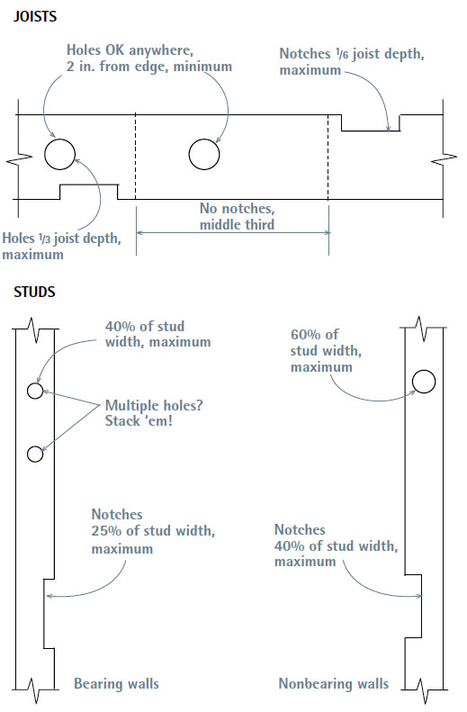 Joists Studs 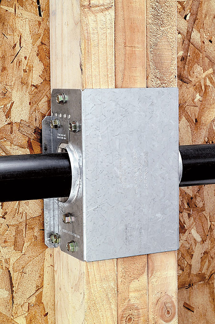 Edge Protection Pipe Slope |
| PRO TIP: If the neoprene sleeve inside a no-hub coupling won’t slide on easily, it may have a small stop lip inside—sort of a depth gauge to stop the incoming pipe in the middle of the sleeve. Soap the inside of the sleeve to reduce friction. You could use a utility knife to trim off the lip, but that would be more time-consuming and you’re likely to puncture the sleeve. |
Insert the no-hub fitting, unroll the sleeves onto fitting ends, slide the banded clamps over the sleeves, orient the fitting takeoff, and tighten the clamps with a no-hub torque wrench. Finally, use a transition coupling, which is a special no-hub coupling that accepts pipes of different outer diameters, to tie the new 1 1⁄2-in. plastic branch drain to the cast-iron no-hub coupling.
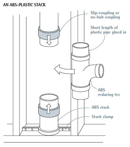
Tying into an ABS or PVC stack is essentially the same, except that you’ll use a wheeled cutter to cut the stack. And, instead of using a no-hub coupling, glue short (8-in.) lengths of pipe into the tee fitting, then use plastic slip couplings to join the 8-in. stubs to the old pipe. (The slip couplings also glue on, with an appropriate solvent-based cement.) Use a reducing tee, such as a 2 by 11⁄2. Be sure to support the stack above and below before cutting into it.
Building out from the main drain
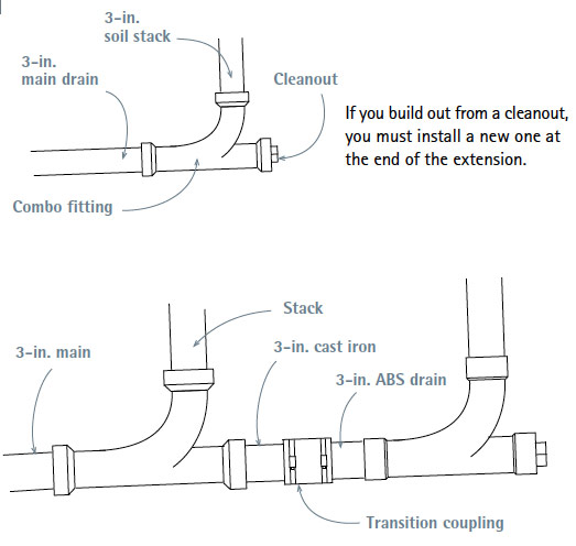
Extending the DWV system out from the end of a cast-iron main drain—where it joins the soil stack—can be the least disruptive way of tying in a new drain if there’s a cleanout at the end of the main drain that you can remove. Before cutting into existing drains, however, support both sides of the section to be cut, using pipe clamps or strap hangers.
The exact configuration of the end run will depend on the size of the main drain, the fitting currently at the base of the stack, the fixtures you’re adding, and the size of the drain needed to serve them. If you are not adding a toilet, the drain extension can be 2-in. pipe, which can be attached with a reducing bushing such as the male-threaded adapters shown in “Extending with 2-in. ABS.” If you’re adding a toilet, however, the extension must be 3-in. pipe, often inserted with a ribbed bushing to ensure a tight fit. If it’s not possible to insert the 3-in. pipe into an old cleanout leg, you may need to cut out the existing combo and install a no-hub combo to build out from.
If the present cleanout is a cast-iron inset caulked with oakum, remove the oakum and the inset and replace it with a short section of 3-in. cast-iron pipe. From there, use a transition (no-hub) coupling to continue with 3-in. ABS plastic.
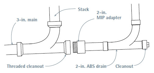
If there’s presently a threaded cleanout opening and you are adding a tub, lav, or sink—but not a toilet—use a plastic MIP (male iron pipe) adapter.
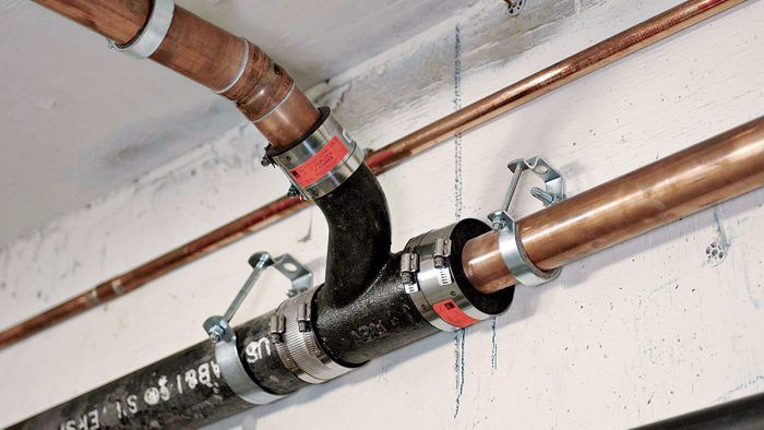
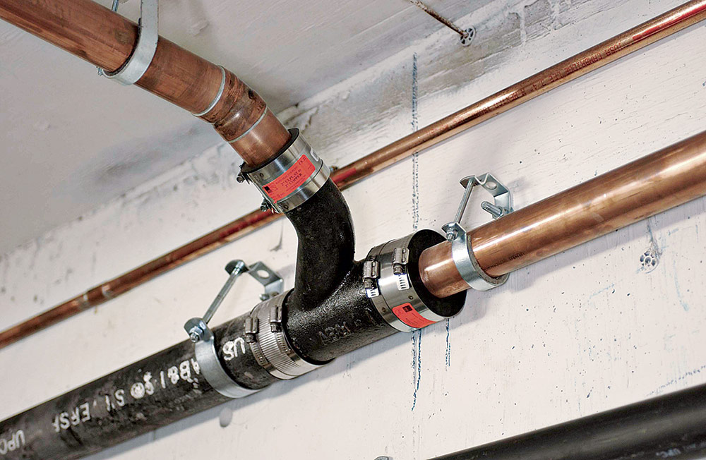
Tying into the main drain in midrun
Before tying into the main drain in midrun, flush the drain and support both sides of the section you’ll cut into. Then install strap hangers to support both sides of the 3-in. or 4-in. drain. Tying into a cast-iron or plastic drain is essentially the same procedure as splicing into a stack, but it requires different fittings. With one hand, hold the no-hub combo fitting you’ll add next to the drain section, and with the other hand, mark cutlines onto the drain using a grease pencil. The cut marks should be 1 in. longer than the length of the fitting to accommodate the thickness of the stop lip inside each no-hub coupling’s neoprene sleeve. (If the main drain is cast iron, use a snap cutter to cut it; if it’s plastic, use a wheeled cutter.)
After cutting out the drain section, use no-hub couplings to attach the new no-hub combo fitting. Slide a neoprene sleeve onto each end of the cut drain, insert the no-hub combo, and slide a sleeve onto each end of the combo. Align the combo takeoff so it is the correct angle to receive the fixture drain you’re adding. Finally, tighten the stainless-steel clamps onto the couplings.
Connecting branch drains and vents
After modifying the framing, assemble branch drains and vents. Here, we’ll assume that the new DWV fittings are plastic.
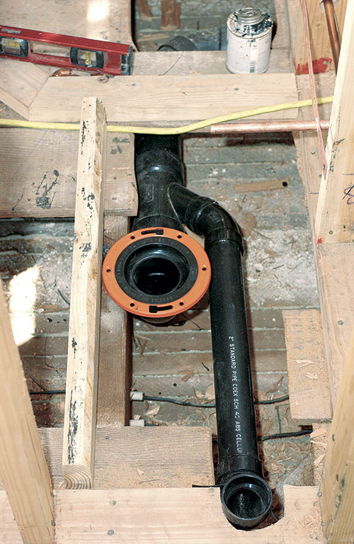
The toilet drain. After framing the toilet drain opening, install the 4 by 3 closet bend, centered 12 in. from the finished wall behind the toilet. Install a piece of 2×4 blocking under the closet bend and end-nail through the joists on both ends. Use plastic plumber’s tape to secure the bend to the 2×4. What really anchors the closet bend, however, is the closet flange, which is cemented to the closet bend and screwed to the subfloor.
Framing for Toilets and TubsYou may need to cut through joists to accommodate the standard 4 by 3 closet bend beneath a toilet or the drain assembly under a standard tub. In that event, reinforce both ends of severed joists with doubled headers attached with double-joist hangers. This beefed-up framing provides a solid base for the toilet as well. If joists are exposed, you can also add joists or blocking to optimize support. Toilets. A minimum 6-in. by 6-in. opening provides enough room to install a no-hub closet bend made of cast iron (41⁄2 in. outer diameter) or plastic (31⁄2 in. outer diameter). The center of the toilet drain should be 12 in. from a finish wall or 121⁄2 in. from rough framing. If joists are exposed, add blocking between the joists to stiffen the floor and better support the toilet bowl, even if you don’t need to cut joists to position the bend. Bathtubs. A 12-in. by 12-in. opening in the subfloor will give you enough room to install the tub’s waste and overflow assembly. Ideally, there should be blocking or a header close to the tub’s drain that you can pipe-strap it to. To support the fittings that attach to the shower arm and spout stub-outs, add cross braces between the studs in the end wall. To support tub lips on three sides, attach ledgers to the studs, using galvanized screws or nails. Finally, if there’s access under the tub, add double joists beneath the tub foot. |
The flange is screwed to the subfloor, yet it will sit atop the finish floor when it’s installed. If the finish floor is not in yet, place scrap under the flange so it will be at the correct height. If, on the other hand, the flange is below the finish floor, you can build up the flange by stacking plastic flange extenders until the assembly is level with the floor. Caulk each extender with silicone as you stack it, and use long closet bolts to resecure the toilet bowl. (Check with local codes first because not all allow extenders.)
Once you’ve secured the closet bend, add pipe sections to the bottom of the bend, back to the takeoff fitting on the main drain that you installed earlier. Maintain a minimum slope of 1⁄4 in. per ft., and support drains at least every 4 ft. Dry-fit all pieces, and use a grease pencil to make alignment marks on pipes and fittings.
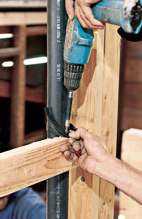
Other fixture drains. Run the 1 1⁄4-in., 1 1⁄2-in., and 2-in. fixture drains up from the main drain takeoff. Drains must slope at least 1⁄4 in. per ft., and all pipe must be rigidly supported every 4 ft. and at each horizontal branch connection. Support pipes with rigid plastic pipe hangers, or plastic-pipe strap, as shown. Support stacks at the base and at midstory by strapping or clamping the pipe to a 2x block running between the studs or by using stack clamps.
 |
 |
Run the tub branch drain to the subfloor opening where the tub trap arm will descend. Pipe stub-outs for lavs and sinks should stick out into living spaces 6 in. or so; you can cut them off or attach trap adapters later. All branch drains end in a sanitary tee. The horizontal leg of the tee receives the trap arm from the fixture, and the upper leg of the tee is the beginning of the branch vent.
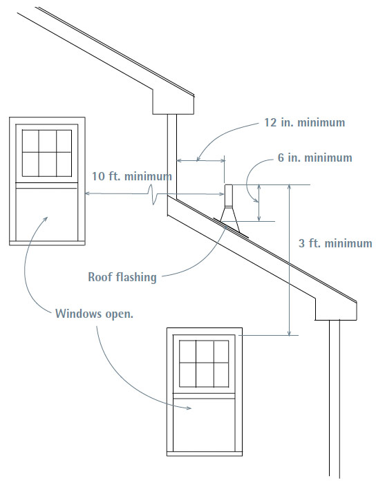
Vent runs. Next, assemble vent runs, starting with the largest vent—often the 2-in. or 3-in. pipe rising from the combo fitting below the closet bend. Individual branch vents then run to that vent stack, usually joining it in an inverted tee fitting, typically 4 ft. to 5 ft. above the floor. Support all stacks in midstory with clamps or straps. Horizontal runs of 1 1⁄2-in. branch vents must be at least 42 in. above the floor, or 6 in. above the flood rim of the highest fixture, and those runs typically slope upward at least 1⁄4 in. per ft. Continue to build up the vent stack, with as few jogs as possible, until it eventually passes through a flashing unit set in the roof. For code requirements at the roof, see “Vent Termination.”
Testing the DWV system
Once you’ve assembled all pipes of the DWV system and connected it to the sewer main—but before hooking up fixtures—test for leaks. A common test is to fill DWV pipes with water, after capping the stub-out for each fixture drain and blocking the combo fitting at the foot of the building drain—as described later in this section. Use a garden hose to fill the largest stack: All DWV pipes are interconnected, so you need to fill only one stack to fill all. Should you see leaks, drain the system, fix the leaks, and refill. If you see no leaks, allow the water to stand at least overnight or until the inspector signs off on your system.
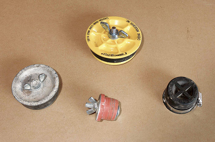
There are several types of pipe cap. Reusable rubber caps or plugs eliminate the need for gluing. A jim cap fits over the end of a pipe and tightens with a ring clamp. Test plugs fit into pipe ends and are expanded by a wing-nut assembly. The most common and least expensive, however, is a glue-on cap that fits inside a DWV pipe stub. Allow pipe cement to dry a day before filling pipes with water. When the test is completed, drain the system and cut off the small sections of drainpipe in which caps are glued. Where a stack is several stories high, this is the only type of cap guaranteed not to be dislodged by a weighty column of water.
 |
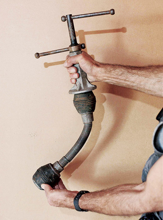 |
The linchpin to this pipe-filling test, however, is a double dynamiter, a spring-loaded double test plug that fits into the T-Y combo at the foot of the building drain. As shown in the photo, this tool has two rubber balls that can be expanded or contracted by turnscrews on the shaft. Insert the balls so that the forward one lodges in the drainpipe, then expand that ball; the second ball should block the open leg of the combo. To release the water, contract the balls of the double dynamiter in the order in which you expanded them. Loosened, the forward ball will allow the test water to run down the drain; releasing the second ball allows you to remove the tool. Label the respective turnscrews so you don’t confuse them: If you release the second ball first, you may get a faceful of water.
If there are finish ceilings in place below new pipes and you don’t want to risk wetting them with a failed connection, use an air-pressure test in which all openings (including stacks) are sealed. Typically, an inflatable bladder attached to a gauge is inserted into a cleanout at the base of the soil stack, and air is pumped into the DWV system. If the gauge shows no pressure loss over a given period, the inspector signs off.

Excerpted from Renovation, 5th Edition (The Taunton Press, 2019) by Michael Litchfield and Chip Harley
Available at Amazon.com.

