How can I convert the support that a pine 8″ x 8″ x 6′ provides, into steel? To save headroom under a barn I would like to remove the 8x8x6’s (which are there to provide additonal support to longer, parallel running 8×8’s directly above them).
Another way to describe this; I have a conrete pad with a post that sits on top of the pad. Then that post supports a 8″x8″x6′, which in turn helps support a parallel 8″x8″ ~ 18′ long. I would like to bolt a 6′ piece of steel directly to the 8″x8″x18′ to save on headroom. I am limited to angle iron that that is 4″ tall. I was thinking of 2 pieces 4 x 4 X 1/2″ (6′ long), one on each side of the 18′ 8″x8″. How can I confirm this?
Thanks!


Replies
It's hard to make positive judgement without a picture. It sounds like you are describing a concept similar to a column capitol...it sounds like the designer was trying for extra shear strength at the column. What doesn't make sense is that the compression perpendicular to the grain (which often controls the design) is the same. Your angles will provide both increased shear capacity near the column, and also help distribute the columns point load (think upside-down) to the beam. Those are very robust angles and should work fine. Post a picture if you can.
Thanks for the reply! I will take a picture when I have a chance in the next week or so; I think that will be more helpful to show what I am trying to resolve. That being said, I think you understand what I am trying to do.
Chris
convert the support that a pine 8" x 8" x 6' provides, into steel?
Well, Southern Pine gives a low value of 550psi for parallel to grain for pine. Multiplying that by the 55.5 square inches of an 8x8 is 28,900#
A 6' tall 4" concrete-filled lally column rates to around 33kips, or about 33,000#
Of course, I do not have my AISC book handy for "plain" pipe & tube columns--but a stock lally is likely a better answer.
I think I might be totally misunderstanding his problem --- I've been thinking he's trying to replace some sort of beam, not a column. That photo should help!
A beam is how i read him too
Welcome to the Taunton University of Knowledge FHB Campus at Breaktime. where ... Excellence is its own reward!
been thinking he's trying to replace some sort of beam, not a column
Yeow, that bends my perception right round. 6' is a short beam, and 8x7 is awful "square" for beam--all of which likely added up to "column" in my perception.
If it's a beam though, HSS 8" square tube ought to work, oughtn't it <g>?
Hmm, since the "kind" of pine wasn't specified, probably could weld up four 4x4x3/8, "fudging" the weld to get the exact timber size and still work (if with no headroom gain <g>).Occupational hazard of my occupation not being around (sorry Bubba)
I'm reading it as a "bolster beam", or a short beam making a "T" on top of a column.
The real beam is sitting on top of it, parallel with it.
Mike, That has been my perception as well.
"Poor is not the person who has too little, but the person who craves more."...Seneca
angle iron won't do much for you but you may not need anything at all.
What you do need is an engineer to calculate this for you based on how this buiolding will now be used. As a barn it was probably planned to handle many tons of hay above and build by seat of the pants engineering, so replacing what is there now is the wrong approach. For instance, if thios will will be for say an art studio now instead of a haymow, it iprobably vastly oberbuilt.
But this may also be a situation where these elements handle some lateral load too, not just the vertical live laod.
So you need to have it all assessed for the planned use.
Welcome to the
Taunton University of Knowledge FHB Campus at Breaktime.
where ...
Excellence is its own reward!
I'm an ex mechanical engineer so I might be able to help you. But I really do need to see a picture because I can't understand the problem as you've described it so far.
"How can I confirm this?"
There are several guys here hoping you can confirm some details if you can read the thread through again
Welcome to the
Taunton University of Knowledge FHB Campus at Breaktime.
where ...
Excellence is its own reward!
Agreed. I'm looking to get a picture(s) posted because I think that will help to clarify what I'm getting at. If I can't find the pictures I am looking for soon, I will go take new pictures. Thanks.
If the "bolster beam" description (per Mike) is accurate, then I think the lower 8x8 is acting as a stiffener; it effectively reduces the span of the 18-footer above it.
By matching the resistance to bending, I ran some numbers and figured that your proposed L 1/2 x 4 x 4 would be an adequate substitution. I'll walk through the numbers here later after you get a chance to post the picture -- I want to make sure that the situation matches my assumptions before spending a bunch of time posting the numbers.
OK, first let me say thanks for your patience!
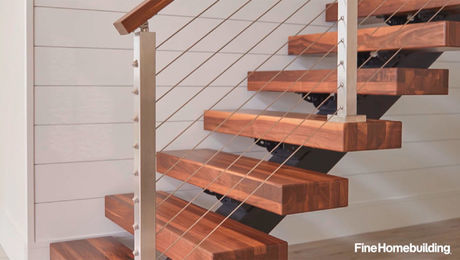
Here's the picture. As you can see in the foreground there is a vertical post that supports a horizontal 6' x 8" x 8" beam. You will also notice that there is a ship lapped joint being supported on the left by this 8" x 8 " beam. (BTW same scenario in the background and in a few other places).
Now there is no point load coming down on the ship lapped joint, it comes down directly onto the support post. In the end though, we know the 6' x 8" x 8" (which helps the longer 8 "x 8" beam above it) has done the job well for many years. It just comes down to replacing the 6'x 8"x 8" to gain headroom. Hopefully this helps!
View Image
Edited 5/22/2007 6:24 am ET by Mike_Maines
Mike,
When attaching a picture here, how do you get it to show directly as opposed having to click on it?
Do the usual "attach files" thing to get the picture attached to your message.
Click "preview message."
When the message comes up, click on the attachment.
When the picture comes up, copy it (I use control-c).
Use the back button on your browser to get back to the preview screen.
Click on Revise.
In the message field, paste the picture file.
It sounds like more work than it is ;-)
Thanks Mike!
So here's my interpretation: I think that the 6-foot 8x8 beam is acting as a stiffener for the longer beam directly above it. In this sense, the system is like stacked leaf springs on an old suspension design.
If that is a correct way of looking at the system, then I think all we need to do is determine the maximum bending strength of the current pine 8x8 and compare it to a steel substitution.
The relationship between bending moment and stress is given as
M = Ió/c,
where M = bending moment, I = moment of inertia, and c = distance from extreme edge of beam to neutral axis.
You mentioned using steel angle iron... L 4x4 x 1/2 has a value of I = 5.56 in^4 (from tables), and c will be 2" (half the depth of the section). I need to guess a little bit for the allowable stress. Typically, steel has a yield strength of 36 ksi. If we assume that it's safe to load it at about 80% of this, we can assume a value for ó of about 29 ksi.
Plugging in these values, we get a maximum bending moment of:
M = Ió/c = (5.56 in^4)(29 kip/in^2)/(2 in) = 80.6 kip-in for EACH piece of steel,
so the total allowable bending for two pieces is about 161 kip-in.
Assuming an allowable stress value for the existing pine is a bit trickier. Values vary widely depending on the actual species and the grade of the beam.
If we work backwards, we can determine a required range....
"I" for rectangular sections is I = 1/12 bh^3. For a net 8" x 8" beam, I = 341 in^4. "c" will be half the depth, or 4".
ó = Mc/I = (161 kip-in)(4 in)/(341 in^4) = 1888 psi
1888 psi is definitely at the high end of the allowable stresses for pine. From the tables available to me, and the picture that you attached, I would GUESS that your beam would support something on the order of 600 to 1200 psi.
The conclusion would be that the two pieces of angle iron you propose would be anywhere from 1.5x to 3x stronger in bending than what you currently have.
Maybe someone here can comment on the allowable stress values for steel and pine, respectively.
The next step would be to determine how to attach the steel to the current long beam.
I wish I could give more of a definitive answer, but hopefully the above will help.
Ragnar
Is this how you are thinking about arranging the steel with respect to the long 8x8?
View Image
Edited 5/23/2007 1:08 am ET by Ragnar17
Ragnar,
That is exactly what I am thinking !!
I appreciate the logical breakdown of your analysis. Very helpful !
Glad my input helped. I did have to make a few guesses, so it would be nice if someone here (like a structural person) could comment on it.
Looking at your picture, it seems like this area is on the ground floor. Is lowering the ground level by a few inches not an option? I couldn't tell from the picture whether there was an existing concrete slab, for example.