another fastener question – Simpton Ties
Hello again everyone:
I’m not sure how upset or worried to be about this, so thought I would consult the board.
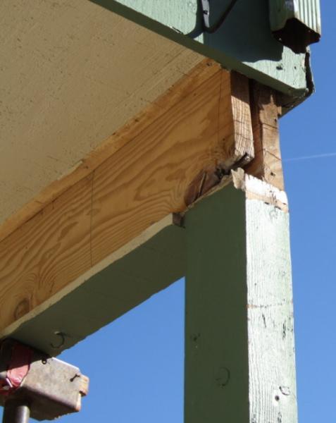
I had a concrete patio removed. The upstairs corner of the house was supported by a post sunk into the concrete that was exposed during the concrete demo. It was determined the post was resting on a stem wall extending from the foundation wall. The top of the post was toenailed into two 2×8’s. During removal of the post, it was discovered that a corner of one of the 2×8’s was missing (presumably due to a large knot in the wood). See Old Post picture. At this point, I consulted a structural engineer who provided a plan showing both 2×8’s should be notched. In order to maintain structural strength, he further stated another 2×8 should be scabbed onto the existing 2×8’s and sections of plywood inserted between the original two 2×8’s. He stated the top of the post should be secured with a galvanized simpson tie with galvanized nails, and the bottom of the post should be anchored using a stainless steel simpson tie using a segment of stainless threaded rod drilled and glued into the stem wall and the post secured to the tie with stainless nails or screws.
I had the same crew back that had started this job (a reputable firm). As is typical here in Colorado, hispanic crews are quite common. The english speaking foreman got them started and then I left for work for a while. When I returned, I discovered a few things I want to run by the board – please see attached photos. The crew was cleaning up.
1) Per the structural engineer, they scabbed the board every three inches down a two chalked lines. See Scabbed 2×8 photo. They did predrill holes in the first scabbed board, but they said the drill bit only partially penetrated the second 2×8. Without predrilling all the way into the original 2×8, do you think I now have nasty splits in the original 2×8 (which of course is now completely hidden beneath the scabbed piece so I can’t confirm this or not). 16d nails were used and driven by hand.
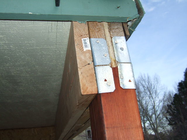
2) Even more upsetting was that they drove nails into the end grain of the original 2×8’s that already had some minor splits. See Simpson Tie photo. I think they predrilled these holes too, but nailing into the end of a board isn’t good in general, is it?
3) minor mistake – although they used stainless 16d nails to secure the new redwood post to the bottom stainless simpson tie, I think they used the same stainless nails to secure the top galvanized simpson tie. The structural engineer had stated on his details to used galvanized with galvanized and stainless with stainless. My hope is that because the top of the post should remain dry (and will be covered with siding again) that galvanic corrosion hopefully won’t occur.
4) I asked about the simpson epoxy for the drilled hole in the stem wall and threaded rod and they said they coated the threaded rod before inserting. I thought drilled holes in concrete were supposed to be pumped full of epoxy and then threaded rod inserted – to be sure the hole is fully filled with epoxy.
I’m not sure at this point whether to pay for another visit by the structural engineer or to question the contracting firm about any of this. Then again, maybe I’m just worrying over nothing – you be the judge.
Thanks for any input.
Edited 3/20/2009 12:00 am ET by Will92


Replies
In addition to Will's question, could someone explain to me the nailing pattern on the sister in the first pic, the two rows down the center approx. a 4 inch spread between the nails.
It seems to me they could have been staggered more. Is this code?
Thanks.
View Image
View Image
View Image
Not an engineer, but I would agree with your take on it. Most often I am given nailing patterns for sistering up lumber that requires a staggered pattern. OP's pic show what appears to be a split developing along the nail line. Also to the OP.: 1)Epoxy should have been injected into the cleaned, brushed and dry hole before the rod was inserted. Rod also must be secured/held in the hole to prevent it from being pushed up and out due to the pressure from the epoxy being displaced until all excess epoxy has been displaced from the hole.
Most epoxy manufacturers have specific instructions contained with the packaging. 2) I am not personally aware of any problems with SS being used with galvanized hardware.
They can't get your Goat if you don't tell them where it is hidden.
The engineer thought the two existing joists were 2x10's and when they discovered today they were 2x8's, he instructed over the phone to sister a 2x8. He thought they were 2x10's because he was only on site once before the siding was removed around the joists. Based on his assumption they were 2x10's, he originally instructed to insert pieces of plywood between the first two joists an a nail pattern of two rows of 16d nails 3" separated, and 3" from edges. When they called him about the nail pattern for the sister 2x8, he said to "just use the same pattern for the sister joist that was originally specified for the plywood inserts."
Those splits in the sister 2x8 were there before they put them up.
Dude .. this is so screwed up I don't know where to start, 'cept to say no one here seems to know what they're doing, ESPECIALLY THE ENGINEER.
Cut out the beam???, the bottom of the orig 2Xs should never have been notched, if those should have been 2 X 8s, they're now only 2 X 6s.
Simpson strong ties need to have the correct fasteners depending on what they were made of.
The nailing pattern shows a complete lack of understanding, the nails should be staggered in the top & bottom 1/4 of the 2Xs height, the opposite pattern on the other side. Should like like character pic below ..
x x x x x
x x x x x
Predrilling nails holes? ... unbelievably stupid.
A beam must be supported by a column of the same width. The new 2 X requires another 2X under it nailed to the side of the column.
Since this is o/s I would have done the whole thing with pressure treated.
I'm not even going to assume this is supported at the other end, all I see is OSB, so I'm just going to say put a column under the other end
A scab is a piece of wood that doesn't run the full length of what it is attached to, these appear to be all one piece as far as I can see.
We typically use the paired AC post caps for column to beam connections. In this case it appears they should have used the ACE type to avoid bending one ear of the AC around the end of the beam and nailing into the end grain. If, in fact, they did use the ACE type, then it is installed backwards. Post a pic of the other side of the connections.
If you are lucky they used 16d nails, otherwise they used the 1 1/2" joist hanger nails. Look for an identifying mark on the end of the nails if they used 1 1/2".
The notch at the end of the original beam was most likely to get rid of the damaged area and provide a continuous seat. The addition of the scab would tend to stiffen the assembly but should have been supported. The OSB filler is just that - a filler - with some, but minimal, benefit.
Since you were replacing the post, it would have been prudent to replace it with a 6x6 for full bearing, adding another spacer to bring the beam out to 5 1/2". For perception, the larger post just looks better. Don't scab a 2x to the side - you won't be happy. Some one mentioned using PT but I suspect you were going for appearance.
Just coating the end of the threaded rod before insertion into the hole indicates they didn't know how to do the job correctly. You don't know if the hole is the correct size or depth or if it was properly cleaned. You can't stick epoxy to dust and you can't fill a void with a thin coating on the rod.
Hello everyone:
Thank you for these replies. I am sort of besides myself here over this.
I hired a large structural engineering firm here in Denver to quarterback this project. I felt this was my extra insurance against mishaps. In fact, the contracting firm (another reputable large firm) said they felt I didn't need the expense of a structural engineer.
When the contractor initially removed siding around these joists, it revealed a large knot in the wood was missing and the post was actually only resting on what the engineer had thought was 2x10's. The engineer told me he did calculations and came up with details showing that a 2" notch should be removed from the other joist to allow a new post to rest level on the two joists. Then, yesterday when they came to do the job, the contractor now spots that the joists are really 2x8's. This precipitated a call to the engineer who then had a conversation with the contractor. I did not hear the full story but apparently the upshot was to scab on the sister 2x8 the full length of the joists. They didn't have the proper dimension lumber so they ripped one down on site with a circular saw. When the hispanic crew didn't know what nail pattern to use for the sister joist, I called the engineer back and he said to just use the same nail pattern as he originally specified for the inserted plywood - namely two rows of 16d galvanized nails spaced 3" apart. The crew started to drive in the nails but many of them bent over so they predrilled every hole. They even did this for the holes for the nails in the new redwood post.
If what you folks are saying here, I am completely frustrarted over this. I spent $1500 for engineering details and have another bill coming for this post job from the contractor. At this point, perhaps a call to the principal engineer of the engineering firm is in order. I see fault with both the contractor and engineer over this.
Should the job be redone??
If it were me yes.
Ir sounds like a cluster..... for sure!
Will, it may be advantageous for you to take some distance photos of the total site and state what exactly it is you plan on doing to better acquaint the readers with the scope of the whole job.
The old adage 'a picture is worth a thousand words' holds true here.
Perhaps some more close up shots at different angles and points will help convey what exactly is going on as well
which will help the posters see details and thus provide more accurate advice.
Cheers
Edited 3/20/2009 12:52 pm ET by rez
Thanks. I got ahold of the principal engineer at the engineering firm and he is going to come to my house to look it over. He definitely had problems with many of things I mentioned - predrilling nail holes, not filling the hole with the set epoxy, stainless nails used for galvanized simpson tie, etc. He offered to call the president of the contracting firm if necessary but I also explained I felt his junior engineer in his firm had some responsibility for this too (specifically not catching those were 2x8's in the first place.
I will post more pictures later today of the general site.
Edited 3/20/2009 1:00 pm ET by Will92
This is certainly some poor design/construction work, but it's tough to say whether or not it's truly unsafe. Regarding the apparent splits on the 2x8 outside sistered board, those splits don't appear to extend down the board, just at the edges. It's not unexpected to split a board when nailing close to the edge like they did. Keep in mind that the peak loading for a beam like this is in the middle, not on the ends. Also since the sistered 2x8 isn't resting on the post, there wouldn't be much of a shear load at the end of the columns where the splits are.I wouldn't expect you've got much splitting in the notched 2x8 boards, perhaps just at the ends again. The notching does weaken those boards some - but not all the way down to an actual 2x6, because again, this is just at the ends of the 2x8s, not in the middle. For nearly its entire length, the beam is a full 2x8 deep. In my opinion, just based on what I'm seeing in the pics and your description, what you have installed now is probably stronger than what you had before, but it was still built improperly. As others have pointed out, I would not have notched the old 2x8s, and the nailing pattern is wrong, plus predrilling the nail holes cuts down on their holding strength.Going with the engineering firm was probably a mistake - for a simple job like this, it should have been overkill (i.e., most carpenters/contractors should be capable of rebuilding that post and beam), but in your case, it got you some bad advice. And since an engineer was involved, the contractor probably felt like he needed to follow the engineer's directions.
Good grief. It's amazing how hard some people can make a simple job.
$1500 for engineering? I'd have torn out that damaged 2x8 and replaced it and been gone by lunch! No sisters...not brothers...just me and the 2x8!
This is a $500 job.
I'm with Jim. You are way overthinking this. It's like hiring a heart surgeon to pop a zit. Two things: a competent carpenter could handle this.What you have, while not perfect, will be just fine.
Well will, While it is not perfect. it isn't anything to lose sleep over. A few minor things and it will be just fine. Let them do that upgrade for free and go on with life.The amt of money paid for all this is the thing to fret over.
Welcome to the Taunton University of Knowledge FHB Campus at Breaktime. where ... Excellence is its own reward!
Thank you everyone.
The contractor seemed willing on the phone to take action to make me happy. I'm pretty sure they would cover additional labor but not sure on materials (their cost, shared cost, or my expense). Therefore, I have posted a few additional pictures for the board (which I apologize for not doing in the first place). (Note the two original joists span most of the entire width of the rear of the home. They go into the wall as shown in the pic, and continue through a soffited area in the kitchen). One additional thing I noted was the engineer's plan called for a Simpson BC46Z post cap and they used two Simpson AC6Z - I don't know if this is important but checked it after someone here mentioned taking a closer look at that piece of hardware. For the bottom the plan called for ABU46 stainless and they used a AB46 stainless. They attached this to the stem wall which extends from the foundation wall.
Some have asked why I consulted an engineer. I felt this was my insurance policy against disaster - this is a load bearing beam and I wanted to be sure the job was done right. As far as a carpenter, I agree. I would have preferred to have found a good independent carpenter but this contracting firm supposedly had qualified people on staff (they specialize in structural repairs so it seemed a good match for the job). For future reference, is there an trade organization, or website, for finding skilled carpenters?
Please take a look at the pictures and tell me if I should move on or have them re-do the job. The engineer said if I wanted a 6x6 rather than the existing 4x6 post, they could either "shelf" the top of the 6x6 to accomodate the sister board, or, notch the sister so the post sits flush on top of all three notched joists. Also, he wasn't sure if they could use the existing epoxied threaded rod with a new 6x6 post base, or would have to shave it off and drill a new hole (which doesn't seem like such a great idea to me since I imagine it would have to be drilled close to the existing threaded rod. Perhaps there is enough room in the slot of a new 6x6 base to use the exisiting rod). One thing with leaving the post alone is that the siders will have to work around the top of it that might come out looking a bit goofy as opposed to putting in a 6x6 post. Can anyone else think of other options worth considering?
By the way, they also predrilled holes for the stainless nails they used on the bottom stainless post base. Should one never pre-drill for nail holes in these posts? Would predrilling and then using stainless screws have been better? I did note the post had some small splits so it seemed reasonable at the time. Also, for the top simpson hardware, the area above where they notched was also split so predrilling here also seemed reasonable at the time. No?
Thanks!
Well Will,
One of the reasons Breaktime exists is to provide a place for homeowners to come and place their questions and hopefully learn a few things in the process.
Those are nice clear pics you provided.
It wasn't clear in your original question that the new post was actually a 4x6 instead of an assumed 4x4, therefore the suggestion to replace with a 6x6 to allow full bearing for the addition to the beam.
With a slight change in hardware you could rotate the post 90 degrees, gaining the necessary support. The position of the post base should probably be changed and the new hole will be further in from the edge of the footing.
I think it would be a good idea to conduct a tension test on the old epoxied rod. It might just pull right out if all they did was coat the rod before inserting it into the hole. If it stays in, then the hole is solid and you can safely drill a new hole next to it. There's also no hard and fast rule that says the post has to be right at the end of the beam.
If you turn the post, I would step the post rather than notch the addition to the beam. Also, use the correct post caps so you don't have to bend the ears of the connector around the end of the beam. They used the T shaped connector, which requires two - one on each side - and is normally used as a connector on a mid-beam post instead of the L shaped which goes on the end posts.
Also, the position of the connector used is incorrect, vertically. The lower ears are factory bent to wrap the post instead of being hammer flattened against the beam. I can see them doing this because of the notched end of the beam but.... since you have an engineer it's his call to sign off on this even though the Simpson tests are performed differently.
There are also some other, more substantial connectors you could use, but even here in hurricane land we usually use those connector plates on jobs such as yours. The top plate connectors shouldn't cost much more than $10 for the pair and the bottom would be less than $20. The Simpson threaded rod with washer and nut is also less that $10. Epoxy is about $30 per tube.