I need to figure what to do when a beam comes to an outside corner of an ICF foundation, and needs bearing.
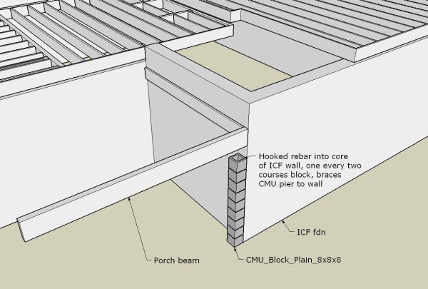
What I am thinking of doing, is widening the footing at the corner, enough to pick up the bearing of a pilaster we can build after the wall pour. Look at the pic and tell me what you think.
The idea is for a pier made of 8×8 hollow block, laid up and filled solid, with embedded hooks tieing it to the wall. The pier here is shown partially completed.
We definitely don’t want to try and make a pilaster form using the ICFs. It would seriously weaken the ICF corner construction.
With my idea here, we can screw an upright 2×6 to the corner of the ICF forms before the pour, drilled with holes for rebar, holes spaced where we want them to go into pier joints, and stick in #4 bar with the outside ends hooked. The 2×6 is ripped down its middle, screwed back together with long screws through its edge, then drilled for the bar. This make for an easy wood dismount after the pour.
I am sure there is an easier way to get some bearing under this beam, and many here can tell us.


Replies
As a followup, we think this ledger attachment, from Simpson, makes sense for the ledgers against the wall.
Anybody have any experience with these, good or bad?
View Image
View Image
View Image
i'D BE DESIGNING A BEAM POCKETBRACKET THAT WOULD HAVE A LEG EXTENDING POURED INTO THE CONCRETE WITHIN THE icf AND FORGET THAT PIER
Welcome to the Taunton University of Knowledge FHB Campus at Breaktime. where ... Excellence is its own reward!
Why are you shouting? The pier is history. ;-)
sorry - I saw that as it disappearaed off my screen and onto yours. That durn caps lock button!
Welcome to the Taunton University of Knowledge FHB Campus at Breaktime. where ... Excellence is its own reward!
see if i can type what i'm thinking. #1 on the ledger running along the wall could you place a 2x10 under that and set anchor bolts into the icf block before you pour,[atcually how i've done this is place the ledger where i want it and shoot a couple drywall screws in to the webs to hold it in place,then just drill and place a 10" bolt every 2']letting it extend out and pick up the outer beam? #2 at the very corner placing bolts up and down along the edge,then bolt a 4x4 standing up and catching the beam? larry
hand me the chainsaw, i need to trim the casing just a hair.
Gene, I don't know as this may help or not but I will offer it.
In some commercial work we have used metal forms that pretty much preclude any penetrations. So (with an engineers advice and direction) have a "weld plate" made up that has anchorage into the poured wall but is flush on the face, then we cast it in place. After the pour we just weld on whatever hanger style is needed for the beam.
Or just make up a similar hanger that can be placed by removing the small amount of ICF needed to place it.
Either way hooks are placed into the pour . Slam dunk for a structural engineer.
Gene,
Is it necessary that the beam be flush to the outside?
My way to do this would be to bring the beam in 3" toward the house and cast in a beam pocket in the ICF corner. The missing 3" can be filled in when the deck is built
I make beam pockets out of any old thing that's laying around but here's some tricks:
1 Make it oversize by an inch or more each way
2 Make the bottom level but chamfer the other sides for easier removal later
3 If your pocket form is not one piece but assembled, make sure all fasteners go in from the outside for easier removal later
4 Wire it in place with a couple of tie wires around a scrap of 1 x 4 on the outside
5 Oil it
6 Carefully mark out its location on the outside of the ICF form
In order to put a pocket form in the corner, you'll have to cut away some foam to get a flat surface to mount it on and some from underneath to get good bearing for the beam. The foam you cut away from underneath can be tapered back to the untouched ICF form over 8" or so.
I have used the Simpson hangers and find them to be raesonably fast to work with, but they are expensive. You will need an impact driver when you install the ledger. Don't waste your time like I did trying to do the job without one. If you haven't got one now, it will pay for itself on this one job.
Lay out your floor framing before you install the simpson hangers in the ICF forms so that you won't have to try to put a joist hanger on top of the Simpson hanger later on. Keep in mind any other penetrations that might have to go through the ledger in case they have to go through in a particular spot.
Ron
Gene - the Simpson product (ICFLW or whateverits called) works really well. My 1st floor is supported on one now.
As for the corner post...
The ICFs I used have a square corner, but the concrete follows a radius inside, so there would be very little to attach to near the corner. I had a similar detail and used a PT 4x6, like your pilaster, as a solution. In retrospect, here is what I wished I had done:
Build the wall like normal. Before the pour, cut 8" of the corner out with a saw (I'd use an electric chainsaw) Leave the foam in where the beam pocket will be. This should expose the concrete cavity - tie into your rebar. Brace the corner with a plywood form corner and then regular bracing. When you pour you will be left with a structural post cast into your wall and a beam pocket for your deck. A much cleaner corner - you could even line the plywood with 1" foam for a thermal break.
-Brian
Thanks for the input.
The issue is that the wall thickness is 11-1/2", with the concrete core centered in that, and the core thickness is about 6".
That puts my wall centerline at 5-3/4" from the corner, and I want bearing right out at the corner so my carrying beam is flush to the ICF foundation wall. What is behind the beam end is mostly foam, thus my idea for the pilaster of 8" halfblocks.
Here is an x-ray view of the pilaster, showing how a hooked #4 rebar is placed at every other block course, right through the joints and a couple feet into the center of the wall core.
View Image
Thinking it through now a little further, I don't see any reason why we cannot build the pilaster of block and mortar, inserting the bars as we go up, before we pour the ICF wall, and then fill the pilaster core with gravel-mix crete when we pour the wall. Voila!
Thanks to another poster for mentioning the steel insert and after-weld. I've done that with poured crete walls, but I don't want to be welding against the foam wall, and we would have to remove most of the corner foam, down to the footing, to get a crete column integrally cast to pick up the insert's reaction.
This block pilaster still seems quick and easy to me . . . but, hey, what do I know. I eagerly await more replies with alternatives.
Edited 1/6/2007 12:16 pm ET by Gene_Davis
Gene - what I am proposing would add a poured concrete pilaster, but inside the very corner of the wall. You would have to take out enough foam to reach the 6" core of your ICF, but not bear on it. I'm attaching a rough drawing - the angled line is rebar.
(top view)
View Image
The idea here is that in the finished product, there is no visible pilaster - a cleaner look imho, unless you are going for a structural look as well. Sorry about the drawing...
I'm pressing the point b/c your post seemed like I wasn't clear the first time. Let us know what you decide. Best wishes.Treat every person you meet like you will know them the rest of your life - you just might!
That's it, Brian! Thanks!
Here's your design, and it is a good one. Ignore the note about doing the cutout from pocket top down to bottom. These pockets are at the tops of the corners.
View Image
The 8-1/2" is as small as I want to go, and we'll make it as large as we can without cutting into the plastic webbing. Here's the plan view. Reinforcement is not shown, but we'll get some verts in there for sure.
View Image
looks like it will work.
What will anchor the beam against siesmic etc.?
Awesome.
Is that sketchup work? I need to learn to do that - your drawings look great. That could really come in handy with conceptual stuff.
Treat every person you meet like you will know them the rest of your life - you just might!
Gene,
I woke up this morning with this thread on my mind.
My first thought was that I was puzzeled at why you are not specing Superior Walls for this job. Clue us in if you don't mind.
I assume that the 'porch' beam runs left from your view and ends up in a like situaton at that end. I also assumed that their is no center pier and as such assumed again that the span of this porch beam is not great. Based on these assumptions, would it be possible to run the porch joists in the direction that the beam is now? Rather than have the joists bear on the porch beam, they would run ledger to ledger, bolted or otherwise fastened to the foundation.
I would imagine that it would be a fairly straight forward project to design and fabricate some type of metal bracket or hanger that would attatch to the foundation after or before the pour that would be fully capable of supporting this load.
Something sticks in the back of my head that there is a roof over this porch even though I don't recall seeing that stated in this thread.
Anywho..........do you have snow up there? DW and I are thinking about a trip up in March, but with the weather being what it is...........'Course, March is a ways off.
Eric
[email protected]
It's Never Too Late To Become What You Might Have Been
Both beams need good end bearing at their connections at the foundation. The one on the eave side of the up-top roof is supporting roof, second floor, and porch floor loads. The one at the gable end is picking up the dead load of some of the gable wall materials, plus some of the point load from the structural ridge. See the dashed lines in this pic.
View Imagegray
The foundation is colored gray where we will remove EPS foam from the ICF forms in order to create pilasters to support the beams at their pockets. See my earlier post for the method we're considering.
Why ICF and not precast? While both have about the same cost for this configuration of house, we have become big fans of the ICF route for a foundation structure, having watched a few get built, and gotten some good feedback from users. Starting from footings in place, if we cannot build and pour this in three days, somebody ought to come up and shoot us. As for the precast option, our good friend who did our big complex one, decided to drop his deal with Superior Walls and not do packages for them any more.
Snow? Not much left here at 2000 feet elevation, but I can still see plenty up higher. Very briefly, before the big melt-off, there was some good XC skiing at Mt. Van Hoevenburg, but it will take another accumulation to make it come back. March? Who knows. It could get good way before then, but maybe not.
Where the dotted lines first touch the upper portion of the porch.........wouldn't a beam from the outside corner of the porch inward to the house be capable of carrying this ridge load?
Thus transferring the load to the foundation and the post on the outside corner of the porch.
You do amazing things with sketch up. I've only recently started playing with it. Not entirely intuitive to me.
Eric[email protected]
It's Never Too Late To Become What You Might Have Been
Wha' program you using? I think I asked you before, can't remember your answer,TIA,Phil.
"If 'tis to be,'twil be done by me."
What we would ask for is a knife-plate connection at the corner. Nothing is easier to cast into an icf wall.
Essentially it's a strip of flat steel molded into the concrete that is beefy enough for the load on the beam. By exiting the wall to the inside edge of the beam the steel strap is easily made to more or less center in the concrete.
In addition to the knife plate, a section of foam is removed around and below it's exit from the wall for better concrete support.
These type of connections are often grossly overbuilt to simplify the engineering, but it's safe to say a 1/4" x beam depth knife plate extending a few feet into the wall and a foot or so onto the beam will support a scarry amount of weight, much more than any wood porch. If the loading on the beam is mostly on the house side this connection seams to make the most sense.
With wide wooden beams that are loaded more to the outside, thicker material is used for the plate, say 1/2", or the knife plate is duplicated on the outside, with the necessary bends to allow it good embedment. If the beam is built up, the knife plate can simply be inserted between the members for more central support.
The ends of the knife plate embedded in the concrete should probably have either a large hole cut or a piece of threaded rod bolted through the end simply to hold against pullout. Not that there is much of a load in that direction, but it's much easier to gard against than to fix if it does slip.
If it were us we'd want the knife plate securely attached to the forms to keep it exactly where it's needed.
Those familiar with ICF walls know how much movement there can be once mud is placed, so make sure there's enough bracing to make sure the corner is plumb when you're done.
The best part is a carpenter can pre drill holes, modify ICF foam, and secure a knife plate in less than 30 minutes. When placing the beam it probably takes the same carp less than 30 minutes to do any slight shimming, drilling, and bolt up. The design of the knife plate is such that the beam is clamped in place and the holes drilled in wood with everything lined up.
As for the Simpson ledger brackets for ICFs, they are tops and by far the most cost effective way for moderate or highly paid labor to build in ledgers.
Beer was created so carpenters wouldn't rule the world.
If you are working with an engineer who is unfamilar with knife plates and wants something else there is another bolt-on option almost as easy. A simple piece of angle is bolted to the wall with epoxied threaded rod and to the bottom of the beam with 1/4" Simpson lag screws.
The foam on the corner is tapered back from the inside so a square concrete pad exists where the beam butts into the wall, 6" or so to the sides and a few feet below. Essentially you're building a projection that extends the contrete to the outside of the foam enough to support the beam load.
As a rule of thumb we'd roughly match the angle on a tapered-top ICF block for tapering the foam under the bracket. To the sides you'll need as much concrete as possible since the engineer will probably require the epoxied threaded rods to have at least 2" of concrete cover.
A combination option of a face bolted knife plate also works well for steel beams meeting an ICF wall anywhere. A "T" shaped knife plate is easily bolted to the center web of the beam with the top of the "T" butting into the wall. We've just used this style of connection for a steel beam in an existing wall with no beam pocket and it is really pretty slick. Our 8x21 beams were spec'ed by the engineer with a "T" shaped knife plate made from a section of the beam, so the knife was 1/4" thick, slightly less in height than the beam's web, and the top of the "T" was around 3/8". Two 5/8" bolts held the beam and knife plate, and four 1/2" threaded rods were epoxied in the concrete, two on each side of the top of the "T".
Best of luck
Beer was created so carpenters wouldn't rule the world.