Hey,
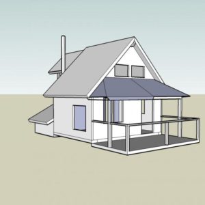
I’m building a small shed roof over part of my cabin deck and would like to use a nice looking joint between the main beam, the beam that runs back to the cabin and the post that they sit on. Timber frame joint would be nice, but I’m a little concerned about losing strength in the main beam. The post is a 6×6 and the beams are 6×8. The main beam spans a little under 16′ and the return to the face of the cabin is only about 4′. I could also be talked into using some nice looking metal brackets and bolting them together. Any ideas welcome.
Thanks,
Andy


Replies
I'm confused about what you need but here's what I just finished. Worked well. I used 1/4" plate brackets to attach the new beams to the existing posts. It's solid.
Bolted Clip Angles
So the two 6 x 8 beams make a "T" connection. I have a joint like that where I used two 3 x 4 x 3/8 pieces of angle iron. The 3" leg has three holes in a vertical row. The 5" leg has a triangular hole pattern with two holes out near the outer edge, and one hole centered closer to the vertex.
Then on the side of the beam that runs through the joint, opposite the beam terminating at the joint, I placed a flat plate of steel with six holes in it. Then the whole joint is attached with 9 bolts (1/2" size) with hex nuts.
It is also possible to eliminate the flat plate by using lag screws for the six screws attaching to the beam that runs through the joint. But this should be very carefully set up and sized so you get the maximum strength and holding power.
I don't have a post under the joint of that type I have here, so, in your case, that post would require a pair of angle irons (clip angles) as well. Generally, I think these bolted steel connectors look just fine if they are designed well and painted. I have a bunch of them in my house and I painted them high gloss fire engine red.
Thanks for the replies.
Yes the beams make a "T" connection and sit on top of the post. Pretty simple, just looking for ideas other than simpson type hardware.
I like the timber frame joints. Nice and clean. How much weight will the dovetail take? It only has a small amount sitting on the post.
The bolts and angle iron would be the easier and faster way to go. I could do some cutting and make the basic parts look hand forged, paint it all black.
The key to making the steel connector joints look good is to use heavy steel. Then painting the connectors with any deep acent color looks good. The nuts and bolts should be painted too. It will not have the meager appearance of the typical steel hanger hardware that is manufactured for the purpose. If you make the pieces custom, and make them heavy, they will look like handsome accents. People that fabricate miscellaneous metals and structural iron can make these type of connectors in small quantities for not too much money.
I primed the angle iron pieces before I installed them with red oxide spray primer. Then when installed and bolted in place, I re-sprayed primer to cover the nuts and bolts. My connectors are on unfiished wood beams, so the spray painting in place required a re-useable spray mask plus some masking tape technique. After re-priming in place, I finished with high gloss spray enamel.
There is nothing wrong with tradtional timber frame joints, but they are quite demanding to execute properly. The heavy iron connectors seem to complement the character of timber beams. This type of joinery was common for industrial structures in the late 1800s and first part of the 1900s. In addition to the angles I described for my house, I also used some big cast iron washers from a timber railroad trestle. They are 4" diameter, and hump up to 5/8" thick in the middle where the bolt head seats. They are for 7/8" diameter bolts. I have these in a different application than where the bolted angles are.
steel connectors
Thanks for all the info guys.
I'm think that I should probably go the steel route on this project and practice my timber framing skills on some less critical projects, like a new out house or outdoor shower, maybe even an extension off of the shipping containers.
kdesign, do you have any pictures of your connectors?
Whatever you want to see
is what you should do. I also have 1/4" plate connectors where I didn't have a post to rest the cross beam. The dovetail is stronger than the lags through the connectors, will support a 2 ton chain hoist for pulling large engines. As Don said, if you need more bearing area, cut it. 3" thick cross beam was plenty for my engine-hoisting need.
Takes practically no skill to make a tight timber joint, just careful planning. That dovetail was cut with a handheld wormdrive saw, finished with a chisel. Faster than cutting, welding, and painting the connectors I made.
Steel Connector Photo
Here is a picture. It is 3-1/2" X 5" X 3/8" hot rolled angle cut to 6-1/2" long with 1/2" hex hd. bolts and hex nuts.
Two More Photos
Here is the back plate for a "T" joint. Two angles are on the opposite side of this through beam.
Next is a cast iron washer from a pre-1900 railroad trestle. It is for 7/8" bolts. Note the anti-vibration locking device for the railroad hex nut. Also notice that "keyhole" feature, which is slotted out of the bolt hole. The washer casting extends its nut face out for that keyhole slot. I have never learned what that feature is for. The only thing I can think of is that it was to permit a nail to hold the washer in position if they were to be installed before the bolts were placed in position. It might have reduced the labor required for installing several thousand of these nuts and washers with the 18"- long bolts.
In timber framing any of the joints are modified to meet the structrural requirements - if you need 6 square inches of bearing surface, you simply make the dovetail wider than if you need 4 square inches of bearing.
bearing surface
Is there any web sites that can help me with timber frame structural sizing? I have a couple books, but they don't touch on how big a joint should be.
The load is small that the short beam will carry. I'm using the 6 by because of looks.
Thanks for all the replies.
....there must be a timber framer around here somewhere that would know.... As a finish carp I generally make fake (non-structural) log and timberframe stuff and wouldn't know about the structural stuff.
No website, I rely on a book from the US Forest Products Laboratory "Wood handbook: Wood as an Engineering Material". Answers questions concerning compressive end loading and tensile end loading. Covers shear and bending moment. It also deals with mechanical fastener strengths and a great deal more. No ISBN number, published in 1974. At one time for sale by Superintendent of Documents, US Government Printing Office, Washington DC. Stock number 001-000-03200-3
It was credited by Hoadley for his "Understanding Wood" ISBN 0-918804-05-1 A very good Taunton publicaton but not one that will answer your specific questions.
The people I know who call themselves timber framers just go by rules of thumb. Overbuilding is easier than doing the math.
Thanks for the book reference
VaTom wrote:
No website, I rely on a book from the US Forest Products Laboratory "Wood handbook: Wood as an Engineering Material".
Tom, thanks very much for the mention of the book. It looks like they update it every few years, and the 2010 edition is available on-line for free. The URL is
http://www.fpl.fs.fed.us/products/publications/several_pubs.php?grouping_id=100&header_id=p
It looks like they do still sell the wood edition too.
Excellent!
Thanks for digging that out. Reference sources are critical for those of us who like to operate on the fringes. Check out these oak rafters. Interesting to set solo.