Can you really frame w/ Chief Architect?
I am about to pull the trigger on a buy of Chief, and have been hanging out on some sites that do Q&A, have training videos, etc.
Warning: If trig and solid geometry were world-class boring when you were in high school, then don’t read on. If solving roof frame problems aren’t your cup of tea, stop right now and read something more fun.
I am doing this because I hope it will be a faster route to the kind of working drawings (plans, sections, elevations, etc.) needed by some clients, and I hope a quicker route to the kinds of interior renderings needed for sales proposals to other clients.
I’m not throwing Sketchup and my 3D CAD package out the window, though, because each has a good reason to be in my tool kit, and there are ways that all three can integrate. Or at least I hope they can, with Chief.
The question here is whether you can really frame with Chief, or more pointedly, can Chief be used to produce the detail I have used in past on complex framing problems. I call them complex because I never really learned the classic way to cut complex roofs, and have always used CAD of some type to figure the cuts for anything other than simple commons. I could probably buy a CM Pro or something similar and figure out how to do everything, but I frame so infrequently it just isn’t worth it.
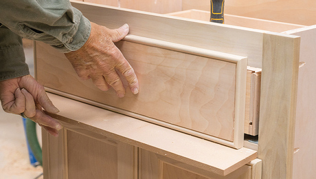
Here is a framing problem that comes from a tutorial I saw on a Chief site, in which the demonstrator shows how to use Chief, to roof over a bay bumpout, with what he calls an “Arizona hip.”
The first thing I thought when watching is, hey, I’ve seen that roof and bump on most everything they throw up around here, when doing some hedge fund guy’s McCamp on Lake Something-or-Other. Why isn’t it called an “Adirondack hip?”
Well.
Let’s get started. Three sides of an octagon, all equal of course, make up the bumpout bay along an exterior wall. The roof for this bump is to match the 10:12 pitch of the main roof behind it.
The Chief tutorial showed how the use of the MAKE ROOF and JOIN ROOF PLANES tool, plus what I will call the LASER LINE tool, all combine to roof the bump with five roof planes, and three of those planes are 10:12, but two are “adjusted” to something slightly different from 10:12. In the tutorial, the front plane of the bump is a 10, as are both planes of the level-ridged “reachout” roof, but the two side planes of the bump are not a true 10.
I did a roof for a bump in Sketchup, and my method arrived at something different. In my result, all three planes of the bump have 10-pitch, but the reachout comes out at close to 10.75 for the pitch. Here is my model.
I could further develop this SU model (it would take me a little time) and figure every angle and length dimension for all the parts needed to frame this as shown.
What concerns me about Chief is that when I show the Chief tut to the PhDs of roof cutting over at the JLC Forum, Rough Framing site, they pull out the trig books and show me that neither my Chief tut nor my Sketchup method matches the way a card-carrying roof cutter would do it.
This pic shows the Joe Carola math (I believe Joe has taken the screen name Framer here at Breaktime.)
I believe that in Joe’s solution, all five planes are a 10. Note that his valleys take a little dogleg when they run out over the hang. Note also that in my SU solution, all five planes are triangular, while in Joe’s the two side planes of the bump are not. The author of the tut for Chief gets a solution with five triangles.
Since I know there are some Chief users here, I will ask you to comment on this. The question is, “Does Chief give you dead-accurate roof planes, and therefore dead-on framing for them, or instead does it just come close enough in situations like this, and that you don’t care, because you are just going to cut it like Joe does.”


Replies
If'n I'm not mistook, you press the framing button to get the results...
Really? Just push a button? Gag me with a spoon.
You a Chief user? Or a jokester?
View Image
"A stripe is just as real as a dadgummed flower."
Gene Davis 1920-1985
It's been a few months (like 20) since I used it, but yeah, they have a button on the tool bar that you press. This is in version 10.
Blue and/or Mike should answer the question.
Heres what was generated with the push of the framing button. Of course, I had to view it using the camera tool. Then, I moved some of the bay members to show how I normally frame a bay. Note that I don't put commons in where most people do. I don't like the commons going to the ridge where the hips meet because it gets to be too much of a cluster there. So, I send the hips to the ridge first, then add in a pair of jacks. I've built at least 100 bays like this...maybe 200.
gene... i don't frame by math much... mostly by framing square and stringlines
but i do know this
<<<<The question is, "Does Chief give you dead-accurate roof planes, and therefore dead-on framing for them, or instead does it just come close enough in situations like this, and that you don't care, because you are just going to cut it like Joe does.">>>
Chief ... as far as i have been able to tell in 11 years... can only draw in the real world
it cannot bend planes
when you grab a roof plane in Chief and pull it or move it, it will do it in 12" = 1 ft. scale
ie: if you can draw it in chief it cannot fudge anything
you may have a plane that is misplaced ( you can move roof pland in 3 axis .... x, y, & z )
but if you look at it with a render camera you will instantly see that you did something wrong
if i had a question like yours, i'd probably go to ChiefExperts.com and ask Dan Bauman what he thinks
a lot of the power users on Chief Users have never framed a thing.. they just draw
and it might be hard to find the right place to address the question on ChiefTalk
but anyways... MEGO when you post some of Carola's calcs.... or even Fusco for that matter...
but .. as far as I know.. if you define the elements correctly, Chief can only draw it correctly
one thing I have come to appreciate about Chief is that I cannot design things that don't work...
if I measure existing things correctly and then draw them in Chief I know that anything I design from the correct model will work in the field and anything I tie into the correct model will work in the field
here's a couple things off the top of my head: you define the rafters
you can define the ht. above plate
you define the pitch
once you have drawn a roof plane you can select it, open it and change the axis
you can raise , lower , move laterally , and you move the edges, break an edge,
make holes in the plane
since you already know cad & SU , i think you will be able to use the Chief roof tools pretty fast
Edited 9/13/2008 4:58 pm ET by MikeSmith
Gene, heres my effort at figuring out how CA works. Please note that I'm still a novice at the roof tools and your little challenge was a nice diversion from the terrain challenge that I was wrestling with.
Here's a pdf showing:
Top left- Chief's auto roof too creating a weird slope on the ridge.
top right- I manually altered the slope.
bottom right- the elevation view showing that I'm missing the ridge now.
bottom left- the plan view showing the basic geometry.
The dimensions verified my first gut feeling when I looked at your SU dimensions. I didn't think the overhang would be 6' if the wall was 6' and the overhangs were 12". I think I've made that mistake in real life when I tried cutting the soffits to that length using the wall as my model. I might be wrong though.
Gene,
I have not used CA for 8 years.
I agree with Mike Smith. Chief draws in full scale and prints out scale drawings. They are precise.
And they are acceptable, maybe. I will depend on what you expect. Lesser pitches on the wing walls crowd the roof plane to the plates by reducing the HAP. If your using 2/8 or greater rafters on the whole roof then it’s not a real issue. (The Frame button should reveal this.)
Both the drawings are different enough to see different things happening.
On the CA camera view with the equal wall lengths;
If you moved the wing hips over to incorporate Joe C’s dog leg you should end up with 5 equal slopes.
On the colored plan view; to create equal slopes;
The common run will need to be determined for a true equal lateral octagon based on the width of the bay’s face wall, and the equal wing wall slopes will form a dog leg valley and hip intersection further up the main slope. The regular valleys formed by the common pitches at the bays ridge and main slope will intersect with the other true octagonal valley and hip lines further up the main slope. All the slopes will be equal but the ridge is quite a bit taller. Like a tall Hat.
I hope some other framers chime with their insights.
Gene,
This roof is from a bay roof that has all equal sides of 6'. It's just a slice of an octagon roof. Keep that hip and valley at the inside corner of the 6' side walls and you will have all equal pitches of 10/12 commons, 10/12 commons coming off the ridge into the 10/17 valleys, and 10/13 for the 4 bay hips.
View it as an Octagon and you will see what I mean. I drew the rest of the Octagon in blue so you can see how everything is equal.
Gene,The issue you are having is due to the overhang. In the tutorial of the Arizona Hip as long as there is some type (value) of/to the overhang Chief will alter the pitch of the hip and valley coming into the eve between the main roof and the bay. If you look that the tutorial, near the end, you will see that the hip and valley move out to the intersections at the eve’s of the main and the bay roofs. This is technically correct since you are always framing to the top of the roof surface.If you set the overhang to 0 you will see that the plan of the bay is identical to Carola’s plan that Chief draws. http://www.josephfusco.org
http://www.constructionforumsonline.com
Thanks, Joe. I know that I can trust that Chief will give accurate geometry for roof planes and their intersects, and I fully understand what is going on in the LouisF tut.
This roof presents an interesting problem, and there are three (at least) solutions to arriving at the five intersecting planes.
In the JoeC and LouisF solutions, 10-pitch reachout roof planes are sprung from the fascia intersects and plate intersects, respectively. The solution I did with Sketchup solved for the ridge height using equal 10-pitch planes for the three front octagon pitches. That solution gives the same ridge height as the JoeC solution.
The diff between my SU solution and the one from JoeC is that I run a straight valley down to the o'hang intersect each side, whereas JoeC bends his, so that his four hips are the same pitch, match the pitch of his frontside valleys, and his topside valleys are classic x/16.97s. Mainlining the valley is what causes the reachout pitch in my solution to steepen.
So now I am wondering, as a soon-to-be Chief user, how can Chief do the roof to yield the JoeC solution? Or does it matter? Would most framers just look at the plans showing a LouF roof, and just frame it per JoeC?
All this software has its funny quirks, doesn't it? And the users that hang out at the forums, aren't they something? As someone who actually cuts rafters from time to time, I would want my models to represent reality and capture best practice methods.
From what I get by reading many posts at ChiefTalk and ChiefExperts, most all there are plans drawers and not builders. I got a kick out of the email response I got from Lou Fernandez when I asked him about some of the fine points of difference in framing the AZ hip, JoeC versus his video. He said, "I have far more better things to do with my time than answer this."
I got a parallel take on things when participating in the forum at the Thermwood eCabinets site. It seemed to me there that the great majority of forum posters were interested in how to draw and render things using the great free software they got, than how actually to build cabinets using CNC machinery.
View Image
"A stripe is just as real as a dadgummed flower."
Gene Davis 1920-1985
Gene,I've looked at Joe C. solution when he first put it up and I'm still not sure I get it since the solution should be to the roof's "upper" surface. I think he commented that if you wanted to have a cathedral ceiling in the bay that was the way to frame it. If you develop SU model further you can see the effect of framing to the two different points.http://www.josephfusco.org
http://www.constructionforumsonline.com
I can answer you from my framing perspective Gene. The plans that I've worked off never provided enough detailed working drawings of the components on roofs like we are discussing. Essentially, the planviews and elevation views on the plans represent what one architect tells me "design intent". That basically leaves the detail of the framework up to the mechanic onsite and any method is acceptable as long as it meets code. Occasionally, on very high end jobs, the details of many of the components on the houses are drawn. Even then, we often would substitute our techniques where applicable because quite often the designs generated by cad operators miss some field realities. With that preamble, I'll explain how I've done them. I look at the elevation view, note the roof slope, note the overhang width and then get down to business. Even if there is a section drawing somewhere, I rarely have used it as my guide because often it's drawn for permitting purposes, not structural integrity puposes. So, no matter how involved you get into drawing the structure of that roof, most mechanics will do it there own way because thats the way that makes sense for them. I'll post my methods (steps) of framing that roof a little late. I got a test to take here.
"Looks Good on Paper"
Exactly. The parameters of a roof like that are given: the slope, the walls, the overhangs. When you look at the elevation drawings and see that the fascia lines are level with the main house, everything is so locked in that there really isn't any fluctuation to discuss....just get up there and cut the roof in. So, I had to think back how I would approach this. It's all pretty basic geometry the way I do it. I'll do a couple drawings to show my method.
Remember these?<!----><!----><!---->
<!----> <!---->
Dovetail Arizona Hip?<!----><!---->
Nope! Never did one like that. My method for framing the bays is this:1) we sheath the main roof. 2) Measure the projection of the bay. That is the length of the ridge3) Cut the common 4) measure up the plywood line the length of the common5) mark a line equal to the length of the common6) strike arcs to locate the center of the bay and intersect them with that marked line7) Nail the ridge to the line at the center where the arcs cross.8) install the rafters. Summary: It's a very easy solution and I wouldn't refer to any construction drawings to do this, even if they were drawn somewhere.
This little bay thing is fun, geometry-wise, because there are multiple solutions.
This pic shows the bay, split so that two of the solutions can be shown.
View Image
The L side has the one done by LouF in his Chief tut. The front pitch, A, and the reachout pitch, C, are 10s, but B has the "makeup" (slightly lowered) pitch. As you can see, the valley is a straight line.
The R side is per JoeC's geometry, with sections D, E/F, and G all pitched the same at 10:12. E/F is one plane, and the line between is not a hip nor valley, and I will explain it in the next pic. The valley takes a dogleg, coming down.
This next pic shows the "gene" solution, which really only differs from the JoeC one in the plane of the reachout roof.
View Image
Here is the arrangement, and I have removed the surfaces F and G, but left their bounding lines. You can see roof plane H, which is part of my straight-valley solution. The pitch of H is steeper slightly than the common 10:12 everywhere else.
The JoeC solution is the only one that makes sense to a card carrying roof cutter, in that all the end cuts are pretty common. All three solutions can be cut and framed as vault-space-under. If the job had metal valley gutters I might prefer one of the two with the straight valleys.
View Image
"A stripe is just as real as a dadgummed flower."
Gene Davis 1920-1985
I'm having trouble understanding why the plane "F" would be maintained on this type of roof application. The two theories I see here is the builder is seeking simplicity, which would eliminate F or they would want authenticity which would then include G and H and then add a small saddle to shed the water on G.
I didn't make it clear, Jim. E and F are in the same plane. The JoeC solution results in sideplanes that are four sided, not three.
Scroll up and see the overhead 2D plan view.
View Image
"A stripe is just as real as a dadgummed flower."
Gene Davis 1920-1985
We probably are thinking of different situations. If the room is framed like a true octogon, the valley will have two segments. If the main roof is sheathed and the Bay roof gets laid onto it, the valley will have one segment...or maybe I'm thinking about it wrong...which has been known to happen LOL! I'm trying to envision if I'd be creating a belly in the roof if I try to do this layon with a total of five planes (the three in on the bay and two that lay onto the main roof). I've made mistakes like that before and didn't notice it till I started sheathing it.
Jim,<!----><!----> <!---->
Your framing tech for your bay roof is virtually the same as I follow too. I shorten the ridge to compensate for the main roofs decking thickness. That’s a recognizable minor omission that I doubt you'd miss in the real world though.
I like your condensed step; 8) install the rafters. I usually string line to the fascia the rest on one side and mirror the results to the opposite. I know that the cuts can be figured from the overhangs instead of the plates but the sequence in the calculations is often more head racking cumbersome on a hot S. Texas day than I often feel comfortable with. You can still produce the same roof in about the same amount of time if you just keep moving.
<!----> <!---->This is one of the few instances that I OTJ it with strings. If I do my home work at the desk I can have it worked out before starting one.
<!----> <!---->I’d guess by the lack of other comments that you are not the only one who has not done a Dovetailed Hip. If the face wall and the wings are equal lateral the hip frames as a true Octagon with dog leg valleys. If not it’s like a typical hip with typical octagons slopes at the chamfered corners. I think they frame easily.
<!----> <!---->I’m not saying the dovetail design should be the preferred design but it is an alternative and there are some advantages to it like. Because all the slopes are equal it is relatively easy to pre cut the entire system from the plan. And they look pretty nice too.
If you’re looking to have some fun with CA you might try framing one of these with it. I, for one, would be interested in seeing what CA will do with it. Both camera and frame views.
<!----> <!---->Some things are easier drawn than built.
Some things are easier built than drawn.
Years ago I work for a guy that would have his in-house plan designer come by my jobs and draw the small details to match my constructions. Simplify and copy.
"I’d guess by the lack of other comments that you are not the only one who has not done a Dovetailed Hip. "I wouldn't go that far with that statement. I have done roofs with the dogleg in the valley. The point I was making is that we all have to make a choice when designing. If we want a true octogon looking roof, it will have 8 sides, not 7. If we are going for simplicity, then 5 is the choice that I would make.
I can’t figure out if that was a trick answer, or if this is a trick question.<!----><!----><!---->
<!----> <!---->
Which roof doesn’t have five sides?
"A little 13th Floor Elevators music please"
Gene,I would also agree with Jim that in all likeilyhood the guy who is framing it is going to have his own way of doing it. Granted, some ways are better then others, but must mechanics will be able to get it done without any additional drawings.As a close on the SU model here's a look at the other side.http://www.josephfusco.org
http://www.constructionforumsonline.com
Edited 9/14/2008 4:28 pm ET by Joe
Gene,
If I had an elevation/framing detail that I really had to have right, I'd make a model in SU for the framers. I don't trust CAs framing option all that much. Yes, all you have to do is push a button but you probably know better than I the old saying about just because it can be drawn doesn't mean it can be built. In SU I'd stick build the area in question using accurate 'material' and then use an exported .jpg to insert into a layout page in CA to become part of the set of professional looking plans that I can use for permitting & building. I like CAs 2d presentation much better than CAs.
I know the roof can be built to the criteria you set in the OP, but I never could get CA to do what I wanted it do. I did make a SU model though. For anyone looking the .skp model, the layer for Frame 1 is what I call the Furniture style roof with valleys cut the traditional way with lots of precise angles. In reality it would probably be built using the Frame 2 layer (with Frame 1 off) like Jim mentioned earlier by running the commons of the roof all the way across the bump (if allowed) and sheathed and then laying a 2x on to create the valley boards to nail to.
john...i wouldn't be using "auto-roof"to draw that in Chief...
but my manual roof tools would get it exactly right
so...i would disagree with your assertion
if you want to draw it in SU ,fine....
but CA will
give you what you need...and it will be as exact as you make itMike Hussein Smith Rhode Island : Design / Build / Repair / Restore
I agree not to use the autoroof but I've yet to figure the solution using the manual roof but I think I might have come up with an idea after I posted.
if you select a roof plane ...you can maneuver & manipulate it lot's of different waysMike Hussein Smith Rhode Island : Design / Build / Repair / Restore
This is Chief's offing for the framing of Gene's roof. It looks pretty good to me. . .http://www.josephfusco.org
http://www.constructionforumsonline.com
Joe, I was not able to get CA to generate a roof like that using the one touch auto build. I'm guessing you used the manual tools, which are usually pretty simple too. What was your technique?
Jim,The technique is pretty straight forward. Using the manual roof tools build the roof using 5 roof plans. Once you have it built, double click the framing tools button and on the rafter tab set your preferences and put a check mark in the "Build roof" box click "O.K." and your pretty much done.http://www.josephfusco.org
http://www.constructionforumsonline.com
Joe, thanks for posting the pic of the CA framing.
Looking at it, I see straightline valleys, which leads me to believe that the roof planes were done pretty much per the LFCompany CA tutorial, that has pitches at 10 for the two planes with the common horizontal ridge, 10 for the face of the bump, and something near-but-not 10 for the two sides of the bump.
Correct?
I don't want to put anybody to work on this unless someone has time to kill and skills with Chief, but out of purely academic curiosity, I wonder how the Chief moves go to generate the roof per the "preferred card-carrying roof cutter" method of JoeC? The one where all pitches are 10, and the valleys are dog-legged?
My own copy, a fully licensed and registered and legitimate V.10 Chief set (upgradeable if I wish), should arrive by Monday, after which I will be struggling up the learning curve.
View Image
"A stripe is just as real as a dadgummed flower."
Gene Davis 1920-1985
gene...i think the chief 10 training that ChieExperts.com has is pretty goodDan Bauman used to produce the training videos for Chief.... but several versions ago they took it in housei always preferred Dan's stuff so when version X1 came out , i took the money i would have laid out for the training DVD's and joined ChiefExpertsthere is a lot of stuff there for free even without joiningMike Hussein Smith Rhode Island : Design / Build / Repair / Restore
Gene,
<!----><!----> <!---->
I Think Joe Carola is more than worthy the respect that he gets from the construction related online forum communities. He’s a top gun roof cutter by my standards too. But like anyone, he can make mistakes too.
<!----> <!---->
I have posted a question to Joe Bartok regarding the Irregular Arizona Hip you reference in this thread over on your thread at JLC. The roof scenario is a brain teaser for sure and it took me some time to analyze it. I think I found a problem with it.
<!----> <!---->
The problem with it becomes apparent when modeling it in SU. I would imagine That CA will also have problems trying to generate the roof as you are attempting to. One thing that I noticed about SU is if you draw a four sided shape in the same plane (w/same layer on) it will automatically fill with color. If the lines are not in the same plane it will not fill, and to check the flatness of the plane you can draw a diagonal line in the shape and if it fills, it creates two planes, that are not in the same plane. There are some line layer issues in SU that can also keep shapes from filling too. So I have had to copy and paste the shapes lines away from the model in some instances to find the problem.
<!----> I hope I have not made an error in my analyses. I hope Joe B. will either confirm or correct my assumptions needed to make the geometry work.
<!---->
Hope this helps you and doesn't hurt me. (I have been known to make mistakes too *and sometimes they sting a little bit.)
Edited 9/18/2008 11:03 am ET by MrJalapeno
I think I know what we've done different. I think I first auto built, then attempted to add manual roofs, which gave me a different result.