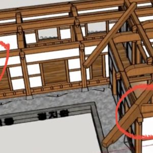
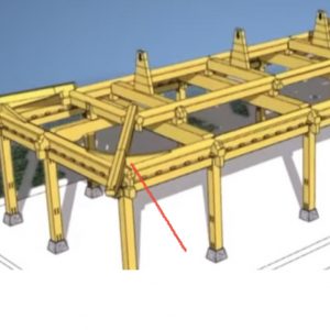
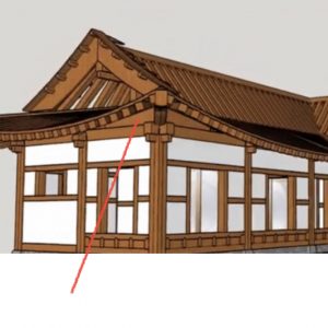
Hi guys, I have a question. I’ve been doing lost of research for months actually trying to figure out how the Japanese and Korean curve their roofs and I figured it out and it’s basically done with timber framing but my problem is I want to know if it’s even possible with stick framing? The closest I’ve gotten to figuring this out is a Dutch Gable roof with very tall hip rafters and a wood wedge on the top of the wall corners forcing the rafters to gradually curve up depending on the wooden wedge. Attached is an example of what I mean. Do you see in both images on the hip rafter on the bottom part where it’s resting on the top of the wall there are wooden wedges on both sides of the hip rafter and those gorse the common rafters to gradually angle upwards. It can be done best with timber framing but since I want to do stick framing is this possible with a Dutch Gabel Roof and a 2×18 or 4×18 hip rafter and 2×8 common rafters?
Discussion Forum
Discussion Forum
Up Next
Video Shorts
Featured Story
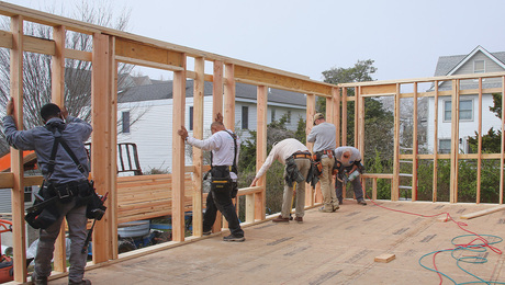
A rear addition provides a small-scale example of how to frame efficiently.
Featured Video
SawStop's Portable Tablesaw is Bigger and Better Than BeforeHighlights
Fine Homebuilding Magazine
- Home Group
- Antique Trader
- Arts & Crafts Homes
- Bank Note Reporter
- Cabin Life
- Cuisine at Home
- Fine Gardening
- Fine Woodworking
- Green Building Advisor
- Garden Gate
- Horticulture
- Keep Craft Alive
- Log Home Living
- Military Trader/Vehicles
- Numismatic News
- Numismaster
- Old Cars Weekly
- Old House Journal
- Period Homes
- Popular Woodworking
- Script
- ShopNotes
- Sports Collectors Digest
- Threads
- Timber Home Living
- Traditional Building
- Woodsmith
- World Coin News
- Writer's Digest


Replies
Wow those wedges are very interesting. That makes sense that they kick the jack rafters up to make the curve. I wonder what the formula is for the change in the angle cut where the jack rafter meets the hip rafter, and change in length as they ride that curve. I have no insights to offer you, only words of encouragement for tackling such a difficult roof construction. Have you considered building a small model of this on the ground based on the scale of the project you are trying to build? It seems like it would be a great way to work out all those angles and plane changes. Plus you would have a template for all the angles and jack rafter lengths.
The straight line belongs to men, the curved one to God.
-Antoni Gaudi
Yes, well not a physical model but a 3d model. This will allow me to view every connection in HD and modify it without having to spend any money on material. Since this is going to be a shed and with me living in California I can only build a 120 square foot shed without requiring a permit. I’m ok with that, I’m making it more for it’s architectural look but the joinery will be accurate for that region. The size of the shed will be 9’ x 13’ wall to wall but the roof will be 15’ x 19’. It will extend 3’ in all directions. This is what I have so far. After I’m done with the design I’ll get it approved by a structural engineer so I can see what type of wood and where he would recommend I add hardware or any changes. In the design the roof only extends 2.5’ but it will have double eaves and including those it will extend 3’. I’ll be posting my progress on this and when I’m done and have the structural engineer approval I’ll give away the digital file if anyone wants to build one.