I already called the engineer. He’s not there right now, but he’ll get back to me. In the meantime…
Looks like I want to drill a 5/8″ hole vertically thru the ridge beam in my shop. We want to install a ceiling fan there and I really do not want to use conduit unless drilling is absolutely out. It’s a big beam… a 6×16 glulam spanning 24 feet. I have absolutely no conception of whether or not you can do such a thing.
What kinds of holes have you drilled in situations like this?


Replies
I'd say that you are significantly weakening the beam, the equivalent of making it 5/8" thinner. Whether it would still be strong enough, I have no idea.
I usually err on the side of foolhardiness, but in this case I would wait for the engineer.
here's my opinion which has no factual basis, mererly my perception. A ridge beam does not crarry a load in exactly the same way, that a standard beam in a standard application carrys a load. the rafters on either side are pushing against each other, which from how I percieve it, does not exert the same amount of downward thrust or weght on a beam supporting a floor for example.
what I have said is nothing more than a thought, the beam will be weakened, but to what extent I have no idea. please wait to hear back from your engineer before you drill any holes.
What, praytell, is causing the rafters to transmit a horizontal load reaction where they contact the ridge beam?
Gene if you would like to think about it, there is a combination of a vertical and horizontal reaction.
because the hypotenuse of a rafter is longer than the run. if one were to remove the ridge and allow it to fall, the length of the rafter would extend past the vertical plane as it fell?
as opposed to a horizontal joist, in which case if one of the supports were removed. the length is already at it's optimum extension. and would wall with a downward arc to the inside of the pivot.
it's because the rafter is at angle that it puts lateral pressure on the ridge as well. I have framed a number of hand cut roofs most times with a big heavy structural ridges, so it doesn't really matter how you put up the rafters, however - if one is framing with with a single ply ridge board, say, if you load up one side of the ridge with all the rafters you will see a lateral reaction. there will be a bow in the ridge and if you want to get rid of it you will have to start over putting both sides up at the same time.
if you don't believe me, then I would suggest to go try it...use a 1x ridge you will be able to see the affects magnified.
I hope that clarifies it.
EDIT:
Gene read Pauls post followed by my response. Paul corrected me on a major difference, which I did not read into from your post. the key difference lies in whether the rafters are leaing against or sitting on the beam. It is done both ways, but I belive it is way better to have rafters sitting on beam, in which case you are bang on.
Edited 12/2/2006 12:48 am ET by alrightythen
Edited 12/2/2006 5:10 am ET by alrightythen
If you have a ridge beam, there should be no horizontal forces at all unless you really goofed something up. I think you may be perceiving something that isn't there, just because it looks like it should be so (i.e. and angled rafter presents a load patially to the horizontal plane). The "ridge beam" is different from a "ridge board". With a ridge board, you have two opposing rafters pressing against eachother but seperated by a 2x board which is used as a nailer. The ridge beam is actually just another top plate.
Think about this: frame an imaginary roof with a 0:0 slope. You have just the rafter going across top plate to top plate. Both sides carry an equal load.
Now, on top of one of those walls, frame an additional 12" up with a new top plate. Make a birdsmouth cut on each side of the rafter and place it back on top of each wall. Does this new configuration press the taller wall out? No. Th reason is that the due to the birdsmouth cut, the load is presented in only one direction = straight down. As far as nature (physics) is concerned, you don't have a diagonal board, you have one board that goes straight up from the shorter wall, then straight over to the top of the taller wall. that is what the two birdsmouth cuts do. If you make your birdsmout cut accurately, you can place a roller on top of each wall and the rafter will stay dead center. Add weight, the rafter is still centered.
BTW, I know this from real experience. When I took it apart, I stripped of the 3 layers (one of them asphalt and gravel) and the 1x6 sheathing boards ... one complete side at a time. When I reframed the ridge beam roof over my garage, I did all of one side THEN all of the other. The beam had no horizontal support at that time, other than the tonails at the base of the vertical beam. Three layers of roof on one side, empty space on the other, no horizontal supports.Rebuilding my home in Cypress, CA
Also a CRX fanatic!
Paul...all what you say makes perfect sense. and I would concur to be accurate.
where the difference lies is the birds mouth. many times rafters do not have the birds mouth at the top and are "leaning" against the ridge board and in some cases the beam. I have seen it.
I totally agree with what you described and also agree that the best way to frame a roof is to lower the beam enough so that it acts in the way a top plate would, as you described.
My brother was once framing a house and wanted to place the 3ply 2x12 ridge "beam" at the top, staggering it in a step fashion, with the joists "leaning" against the beam. the stepped beam was to have the center 2x12 higher to accomodate the roof pitch. said he's seen it in a book to do it that way. I told him I wasn't putting it up and that he would have to go up there himself if he wanted it that way. ( he don't like heights) needless to say the beam got lowered, with a birdsmouth at the top.
So I guess it comes down to how it is framed, if it's leaning then yes there is some lateral forces at work...with a birdsmouth the lateral effects are alleviated.
Great answer...thanks Paul.
Now not only does Dave need an engineer but we do too. The forces on a ridge beam are vertical, gravity. It makes no difference if there is a bird's mouth or a plumb cut. If the beam sags and the top plate is braced, the ridge will be pushed to one side. If the beam does not sag, if it is properly designed to hold the load, the ridge will not move sideways.
Of course, if you have opposing rafters and the ridge beam is undersized or compromised, the ridge will sag and the plates spread. It may take many years for this to happen because the roof is infrequently under a design load and the sheathing will help the roof resist these forces. A drive in rural New England will show many sagging ridgelines in the old farmhouses and barns.
David, we have to "chase" for wires n beams a lot.One pic has a wire run on top of a gluelam w/ a vertical pc of fir, routed out for a chase. A little slot in the beam cap finishes it.The other pic shows the reverse of maybe another option. It's dadoed for an exposed track, but we.ve also done it on the backside (hidden) as a chase. The beam cap also makes a base for the fan. Oh God said to Abraham, "Kill me a son"
Abe says, "Man, you must be puttin' me on"
God say, "No." Abe say, "What?"
God say, "You can do what you want Abe, but
The next time you see me comin' you better run"
Well Abe says, "Where do you want this killin' done?"
God says, "Out on Highway 61."
now I'm worse off then when I started. Paul's explaination made perfect sense to me, but now it seems like I had it right to begin with.
I'm going to go think abou this for awhile...I just got thur thinking about radii and helex formulas, now I have to ponder something I thought I fully understood...but I love this stuff - as long as it doesn't keep me awake at night.
Paul, With any sloped roof there are horizontal forces that have to be accomodated in the structural plan. Those forces can be addressed in a number of different ways, but using a birdsmouth cut on the rafters will not eliminate those forces. In your example of building a flat roof & then raising one exterior wall by a foot, the addition of that slope in the rafter does result in horizontal forces being applied to each exterior wall. Maybe not enough to easily detect while framing, but, nevertheless, it's there. If someone doesn't do a better job of explaining that, I'll try to get back to this later when I have more time.
Paul after reading what the others posted I drew a picture for myself to better visualize. your description threw me with such a shallow pitch to consider. I often find it helpfull to to understand it if I look at an extreme case. when I responded to Gene I, in my mind had been thinking in terms of something more like a 12/12 pitch. which is easier to see that even with the birdsmouth, there are combined forces invlolved.
View Image
if you look at the drawing imagine that the rafter is locked in at the bottom, and that the beam is locked into the rafters at the top. if all support under the beam were removed than the beam could not fall straight down, would it not fall in an arc with the combined lateral pressure and gravity taking effect?
The point is the strengh of the beam is suposed to resist both vertical and lateral forces. I think that there are several factors and it will all depend on how they are applied. The birdsmouth helps to combat lateral thrust, the steeper the pitch the more lateral pressure is increased...in your example of the shallow pitch roof lateral pressure would be very minimaL. with a 17/12 pitch roof it would be increased.
what are your thoughts....and hey lets hear from Gene.
I like your drawing. I still maintain that the ridge beam does not have to resist lateral forces. In reality a ridge beam has some thickness (in this case 6") which would provide lateral resistance. In theory one could design a very deep but thin beam (say 2"x48") which could support the vertical load but would not bow out.
An analogous situation would be a tall 2x4 wall supporting the top of a shed roof. Would this belly out? It could but only by moving the short wall as well. In reality the plywood membrane of the sheating would prevent this from happening once it was installed.
"I still maintain that the ridge beam does not have to resist lateral forces."
"In reality a ridge beam has some thickness (in this case 6") which would provide lateral resistance. "
I not real clear which side your on, your two sentences seem to state two different opinions. your later statement seems to indicate that you feel that there is no lateral pressure.
gravity does provides the force, but because of the angle of the rafter, there are lateral applications. and although I believe it increases as the pitch increases, I think it really is minimal. I think that a birds mouth makes a huge difference. even with your theoretic 2x beam. it works as you say only with rafters being able to rest atop the beam. ie fully or with birdsmouth.
this has been a great topic, and I apologize to the OP for the hijack. I think all the input and thoughts have been great.
Edited 12/2/2006 7:58 pm ET by alrightythen
A question for you, from me, the engineer. It's sort of in line with your issue here of lateral forces on structural ridge beams.
Why is a rafter's loading, and thus the reactions it brings to its bearings, related to its span, and not to its length?
that's a good question... we always have to go to the tables with span... but really , the total load is a function of length
hmmmmm...
of course , the span tables take this into accoutn by having one of the entry points being the pitch... so the length of the rafter is factored in anywaysMike Smith Rhode Island : Design / Build / Repair / Restore
Think about it some more, Mike. Do a calc on an example, say, a 3:12 roof and a 14:12 roof, both carrying a foot of wet snow. Same spans. Which roof is bearing down harder on its plates?
gene.. i already thought about it.. the steep pitch is bearing harder on both the plates & the ridge
the rafter is acting as an evenly weight distributed beam
an equal amount of weight is being carried on the ridge and an equal amount on the wall plate
i was agreeing with you that the total force is a function of rafter length, which is directly proportional to roof pitchMike Smith Rhode Island : Design / Build / Repair / Restore
How much harder? Just gimme a percentage, the 14:12 as a percentage over the 3:12. Spans are equal. Both are carrying a foot of new, wet snow.
the 14 pitch will be about 1/3 more weight than the 3 pitchMike Smith Rhode Island : Design / Build / Repair / Restore
Reactions from the snow loads are equal, no matter the pitch of the roof. And I am finally getting some up on my roof.
Don't size stuff for my jobs, Mike. It'll cost me money! ;-)
Now, I could be wrong. I am a little distracted, being that I am over at iTunes downloading some stuff by Alecia Nugent, which some music writer has dubbed "the most riveting new female voice and stage presence in bluegrass . . . " I agree.
gene... the olde trick question..
i was going to ask you if the snow was normal to the pitch...
but your example is BS
if you have a roof pitch 18' long x 10' wide with one foot of snow on it ( a 14/12 pitch
it is going to weigh more than one 12' long x 10' wide with one foot of snow on it ( a 3/12 pitch )
but the problem is you are not measuring the depth of the snow normal to the pitch, you are measuring it on a plumb line
so... Mike Smith Rhode Island : Design / Build / Repair / Restore
Hey, Mike, relax. Roof snow load is always plumb. Whoever heard of normal?
Maybe if I had done my structural studies over at Brown, I might have been affected by one to many nor'easter, but I did my work over in the flat and boring midwest. I didn't get normalized.
Here's a little pic, rafters not shown. A twelve-inch snowfall, sliced 24-wide, sitting atop a 3-pitch, and next to it, a 14-pitch. Spans are equal at 15 feet. The snow weighs the same on each, thus, equal reactions at bearings from the snow load.
Dead loading is another question, and certainly relates to length, not span.
Next thing you'll make me do, after I have sized my rafters way up, is collar-tie the whole shebang, even though it's got a structural ridge!
View Image
no.. a definition of terms would have been good
if you have a 12" snowfall the snow will be the same on both roofs.. since it covers the footprint of the rectangle
but if you have snow 12" thick on each roof , the high pitch will weigh 1/3 more than the low pitch
suppose instead of snow we say roofing... the high pitch roof will weight 1/3 more than the low pitch
or suppose it was a tile roof...
nope , you didn't say "snow load"
you said
<<<
Think about it some more, Mike. Do a calc on an example, say, a 3:12 roof and a 14:12 roof, both carrying a foot of wet snow. Same spans. Which roof is bearing down harder on its plates?>>
what am i supposed to make of "carrying a foot of wet snow "
nite , gracie
Mike Smith Rhode Island : Design / Build / Repair / Restore
You guys have lost me.
Say you're building a roof: rafters and a ridge board (rather than a 'structural' ridge beam). It's a smallish 1-storey gable-ended house.
Set a pair of common rafters at each gable end, opposite one another, so their upper plumb cuts 'lean' one into the other. Nail their birdsmouths at the wall top plates. Temporary lateral braces keep the rafters plumb and secure from collapse.
Then, you lift your ridge board - it could be a 1x10 - into position. Miraculously, the opposing rafters at each end open a bit, they grab a hold of the ridge, and hold it there, pincer like.
Check for layout and plumb, nail off the rafter pairs at each gable end, then fill in and nail the other rafters. Finish with collar ties. Ceiling joists already in place prevent walls from bowing to the outside.
Observation: The pincer-like action that holds the ridge board in place - without nails even - tells me there is a lateral component to the forces at play.
Incidentally, don't 12/12 roofs shed their snow?
Edited 12/3/2006 12:33 am ET by Pierre1
I'm with ya Pierre. what you say, is essentially the same premise I had in mind when I made my 1st post in this thread...
where I think it gets altered is when Paul brought up the birdsmouth method for cutting the top. also one could plumb cut the rafters have them mate up at the top then set the beam below the rafters, so it's relationship to the rafter's vertical load is increased, or put another way, relationship to the rafters lateral force is decreased.
either way I beleive that lateral force will still exist, it's just a matter of how much and how it has been affected by the different framing medods.
the shed roof was brought up as one good example of how running the rafters over top the wall works in real life, while I think some lateral pressure may still exist it's just not enough to make a difference. where it would more likely be a problem, would be if the rafters were plumb cut where they met up with the taller wall, resting against it instead of on top of it. but we don't do that.
I am waiting to hear the answer concerning the load using roofing as the example.
I know after a day of packing roofing or sheathing for these roofs my back and legs say that the steeper pitch carries more weight and therefore the bearing for that roof is also carrying more weight (or maybe it is mass, I forget now)
Edited 12/3/2006 12:34 pm ET by dovetail97128
The only time lateral pressure exists is when things go wrong - as in the example of the ridge beam sagging. Really, you should imagine the rafter actually growing in length, as that is what is happening in that example when you lower the ridge without moving it out as well.
Lateral pressure only SEEMS to be right, because we expect an angled board like a rafter to exert an angled pressure. But it doesn't. I'll give you a picture, and an example:View ImageThat black square on each example is a 50lb weight. If you ignore the rafter weight (which is different for each example as it is longer or shorter), the weight born on each side will be 25lbs. If there was ANY lateral force exerted by the setup, there would be less than 25 lbs on each side (the force comes from somewhere). The last two examples above are esentially the same construction, just shaped different - but they deliver the force of the 50lb weight exactly the same.
Here is a project for you, because you need a real hands on example to overcome the illusion for yourself:
Build yourself a 3'-4'-5' triangle, but just butt together the 3' and 4' sections Use scotch tape to keep them in the correct position, and cut two 6' lengths for the 5' section - this is your "rafter". Now with one piece cut the birdsmouth where the 3' section is the upright, and the other piece cut the birdsmouth so the 4' section is the upright, as in this illustration:View ImageSo, after you set the rafter on the two examples, you see that neither are pushed out. Now, pound a nail at ANY point along the bottom of the rafter, and hang your hammer from it - does anything change? No. There may be more force bearing one on plate or the other, but the force is still going straight down, not to the side.
Go, try this out for yourself. You will understand why "lateral force" is a mental illusion after you actually do it.Rebuilding my home in Cypress, CA
Also a CRX fanatic!
Thanks Paul for your further input...I've been thinking about doing a mock up. might not be right away, but I will definitely at some point.
EDIT: was looking at your pics some more...what happens if you chop the legs out from under..say for example take a foot off the bottom. the beam or top plate of wall would then tend to want to go outward would it not? ( this goes back to the drawing that I posted earlier.) it seams that the steeper the pitch the farther out the top would be pushed as it fell.
this leads me to believe ( as I already concurred) that what you describe alleviates lateral force. but only because it is structured to do so. when a roof sags from undersize ridges it still has opposing rafters counteracting lateral pressure from the opposing rafters. so it only has down to go.
if you took a 40' long shed roof like your steep version. and took out all the studs from high wall, and left only a single top plate. with an end wall remaining on the two sides. then sight the wall or string a line, I think that you would see that the wall has not only sagged, but has also bowed out.
I think your description relies on design and structural resistance. the design of the birdsmouth alters the dynamics. but also relies on the the strength or structural integrity of the beam, or the wall. if the latter is compromised, and if there are are no opposing forces ( rafters) then lateral forces will play a role.
anyway, great stuff Paul - keep it up. I still would like to do a mock up.
Edited 12/3/2006 1:17 pm ET by alrightythen
the whole purpose of a structural ridge is to eliminate the lateral force
how can you build a cathedral ceiling with rafters if you have lateral force ... any lateral force ?
if there were lateral force it would bow the supporting wall out on both sides .. the only thing holding the wall in place would be the gable ends
no.. there is no lateral force
now .. the birds mouth will give some upward resistance , and it will help to align the structural ridge... but it is doing nothing in terms of supporting the weight
the rafters can just as easily simple rest on their edge
another thing.. the rafters can rest on their edge and never touch the opposing rafter..Mike Smith Rhode Island : Design / Build / Repair / Restore
Mike, I have been following this discussion and I believe what is confusing people regarding lateral forces on the structural ridge beam is the way the rafters are actually attached to the beam.
In order for there not to be lateral force on the ridge beam, the force bearing down on the beam from the rafters must be transferred to the top of the structural beam...i.e. the rafters must be sitting on top of the beam (birdsmouth optional) or they must be suspended on the side of the beam ( using birdsmouth cuts) by hangars that wrap over the top of the beam.
Any other method of attachment allows the rafter to act as a wedge against the side of the structural beam and certainly does cause lateral force on the beam.
Mike, the lateral force you speak of is the one that pushes the walls out, right?
I think others here are also speaking of the lateral force applied to the structural ridge beam or the non-structural ridge board.
I understand that if a structural ridge carries half the roof and snow loads to the (vertical) posts holding such ridge, then the lateral forces pushing the walls out have been reduced in half. Surely, even with a structural ridge, a 12/12 rafter applies an outward (and not just a downward) force to the wall plates. Hence the reliance on floor joists to keep these walls in line. ???
"Surely, even with a structural ridge, a 12/12 rafter applies an outward (and not just a downward) force to the wall plates. Hence the reliance on floor joists to keep these walls in line. ???"
With a structural ridge, if properly sized, there is no outward force on the wall plates. This system will work where there are no floor joists, as in a completely open cathedral ceiling.
Just because the rafters are at an angle to horizontal does not mean that there is a lateral force on the walls or the ridge beam. Take the case of a shed roof with rafters on a 12/12 pitch. There is no force in the roof load that will push the walls in or out. The rafters could be hung off the side of these walls (I can't think of a single reason to do this.) and it would make no difference in the force exerted on the top of the walls. Once the sheathing was on such a shed roof it would be completely stable.
Even on a shed roof my memory of physics and logic tells me there is still a lateral load. This lateral load may be small enough that the fasteners holdilng the rafter to the ridge beam are sufficient to restrain the lateral load. In other words, the world ain't flat!Let's not confuse the issue with facts!
**Just think guys and gals. If a 5/8" x 16" hole equals a Gideon Bible of conversation. A proposed 4" x 32" drilled hole might equal the U.S. tax code.
But that's why we show up here.
**Content for laughs and giggles only.Best to you and yours, Chris.
Some say I know too much.
"With a structural ridge, if properly sized, there is no outward force on the wall plates. This system will work where there are no floor joists, as in a completely open cathedral ceiling."
I follow what you're saying, but find it hard to fathom based on what I've seen.
Seems to me that many (all?) cathedral ceilinged buildings use some sort of mechanical/structural device to keep the walls together. E.g. iron rods or cable wiress with turnbuckles. Granted, these devices are 8', 10' or 12' o.c., but they are there nonetheless. Maybe these rods/cables serve another function that escapes me.
Let's try another anology or example.
Cut a rafter with the ridge cut and a straight top plate cut (no birdsmouth)Now imagine ball bearings set into both end cuts.Now lean the rafter as it should be angled between a flat wall and floorDo you think the rafter will want to 'slide out'?If there are no lateral loads why would the 'slide out' occur.Let's not confuse the issue with facts!
Now cut a 1/4" deep birdsmouth near the top of that "Rafter" and set the BM on a sawhorse.
No more slide out = no lateral force.SamT
Now if I could just remember that I am a businessman with a hammer and not a craftsman with a business.....segundo <!----><!---->
you're in trouble.. you're introducing things into the mix that don't exist
if you could instantly cut both ends of a rafter in a structural ridge so the pices would clear the inside of hte ridge & the inside of the wall.. where would it go ?
it would go straight down.. not out
sometimes structural ridges also have other loads imposed on them ... introducing a lateral force... typically this might be a ridge of an intersecting gable...
or the rafters of an intersecting shed dormer
these lateral forces have to be compensated for.. but in a "common" rafter situation , with a structural ridge, there IS NO LATERAL FORCEMike Smith Rhode Island : Design / Build / Repair / Restore
David,
Just curious - did you ever get a response from your engineer?
Man, ask an innocent question... sure stirred up a good one this time!
Wayne
I left a message on Friday afternoon. We had a foot of snow last week and everyone used it as an excuse to turn into a bunch of sissies and skip work. He'll probably call me tomorrow, and I will post the response.
He's likely to say it's OK, and people will use that as a reason to drill their ridge beams, and then sue me.
Show him this thread and have him straighten us out, if he wants to perform a valuable public service.
yeah ...we clearly need some help here. started out all very peacefully, but if we all weren't so far apart I could see it coming to fisticuffs.
I'll be happy to to be proven wrong in every sense, just to get to the bottom of this..er..or is it top...lateral or vertical??
and sorry bout the hijack.
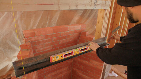
here's a structural ridge on our current job
this one had some temporary lateral forces on it.... a gable dormer, a shed dormer
we lean things against it and it pushes the ridge.... but once those are in place, those forces are supported by the ridge... and in this case, the ridge is supported by the 3 posts... one on each gable end & one center post
Mike Smith Rhode Island : Design / Build / Repair / Restore
ok..you have some good pics there mike.
"we lean things against it and it pushes the ridge.... but once those are in place, those forces are supported by the ridge... "
so you are saying that the lateral forces ( and vertical) are supported by the ridge, meaning they disappear ( lateral force)? which seams to be the argument. in that case where do they go?
if you took out that nice beam and stuck a single 2x4 plate in there supported only on the ends. it would obviously sag, but do you not think that without opposing rafters that it would also bow out a little?
Edited 12/4/2006 12:13 am ET by alrightythen
Hmm, this pot needs some stirring.. anyone considering wind loads in their equations?
;-)
The sheathing on the roof will resist the wind loads unless it is an exceptionally long wall. We brace the walls until the sheathing is on.
so you are saying that the lateral forces ( and vertical) are supported by the ridge, meaning they disappear ( lateral force)? which seams to be the argument. in that case where do they go?
They don't 'disappear'. They are not allowed to be generated.
The lateral forces being discussed in this thread are caused by allowing the ridge end of the rafter to move downwards without being able to move in a true arc, ie also outwards away from the wall.
As long as the ridge end can't move downwards, there is no lateral force.
for a given span, as you raise the ridge height, the rafter length gets longer. Conversly, for a given rafter length, as you lower the ridge, the span must increase.
With a nonstructural ridge board, if the span can't increase (because of good ceiling joists,) the ridge height can't change. OTOH, with a good ridge beam, the ridge won't lower so the span doesn't widen.SamT
Now if I could just remember that I am a businessman with a hammer and not a craftsman with a business.....segundo <!----><!---->
This discussion is scaring me.
First, DON'T drill the sucker! You're taking out 10% of the strength. Generally, there's enough safety factor that you'll get away with it, but your engineer isn't going to answer your phone calls ever again. His lawyer might, though.
Second, engineeringwise, we're talking two entirely different situations here. One is rafters (with a ridge BOARD) and joists (or tie rods) and the other is a ridge BEAM with no horizontal members (no joists or tie rods.)
Rafters and joists make a triangle and the joist HAS* to be there. Imagine two rafters, plumb cuts at the top, seat cuts at the bottom- forget about the tails and the rest of the birdsmouth, forget about the ridge board. Now grab a plumb cut in each hand, butt them together up in the air, seat cuts on the floor and let go. The seat ends slid out and the plumb cuts hit your toes, right?
Now that the rafters are down on the floor, butt the plumb cuts again and nail a "joist" from one horizontal cut to the other- still no ridge BOARD, no nails at the plumb cuts, but you've got a triangle. Stand it up like a gable and nothing slides, because the joist is taking up the lateral forces. Slip your finger between the plumb cuts and it will get mashed. The joist is pulling the rafters together- that's why they don't slide out and why they mash your finger.
Now visualize a floor structure- two mud sills, a girder down the center- and run a joist across, from one mud sill to the girder. No problem- it just sits there- no lateral forces- just vertical. You could put roller skates under it and it would still just sit there.
Now raise the girder a foot. You'll need* a shallow birdsmouth at the girder and a seat cut at the mudsill, but it still just sits there- a horizontal seat cut on a horizontal mudsill, a horizontal birdsmouth on the top of the girder- no lateral forces- just vertical. As long as you have the seat cuts, the mud sill and the girder, you can go to 120/12 and call it The Cathedral of New Jersey, but you won't need flying buttresses or joists, because all the forces are vertical.
But, once that girder goes up in the air and becomes a ridge BEAM, it has to be pretty stout, because it has to take the weight of all the rafters out to the gable ends and the stresses are highest right in the center between the gables, right where the 5/8 hole is. Beams always break in the center unless there's a knot in the wrong place. You wouldn't think of drilling a vertical hole in the middle of a rafter- not even a plumber would do that- so don't do it to a ridge beam.
Now for the "*" part. You don't HAVE to have the joists, but in a while, you'll have one of those sway-backed old barns, because the lateral forces from the rafters will bulge the side walls and the ridge will sag. Or you can add flying buttresses. You don't HAVE to have the seat cuts- the forces are still vertical- but you'll crush the corners of the ridgebeam, the outside of the mudsill and the bottom of the rafter.
Yes, there will be lateral forces from wind and earthquakes- the 6" dimension of the beam takes those. Imagine a 25" deep I-joist- it could take the vertical loads just fine, but you know how floppy it would be laterally.
Sorry to be so long winded, but hey, if you've already read 70+ posts to get to this one, you must like this stuff. If you really want to get a feel for the forces, make some small models- 10 foot 2X4s for ridge beams and 1X4s for rafters and joists, w/ 6d nails. They're soft enough you can really see the deflections and the failure points.
Yer preechin to da kwire, here.
I was God blessed with a gift for seeing forces at play in a structure. A horse whisperer kinda thing I guess.
In the situation described in the OP, I would make two wooden "Cast Iron Hangers" to nail on each side of the beam with a couple of rivet or bolt heads on 'em.SamT
Now if I could just remember that I am a businessman with a hammer and not a craftsman with a business.....segundo <!----><!---->
Now that it looks like we are reaching some sort of consensus on the forces involved (and that's no fun...), let me wade in with another complication. The forces acting on joists supporting pitched roofs are often not really acting horizontally or vertically. We simply "resolve" them that way to make the engineering calculations possible. They are said to have horizontal or vertical components but in fact the forces are often acting on the structural members at an angle.
Edited 12/5/2006 11:36 am ET by fingersandtoes
We simply "resolve" them that way to make the engineering calculations possible
Nah, If someone wanted to they could resolve all forces present relative to the angle of the upper beak of the rooster shilouette on the weathervane of the Whithouse as it was pointing at midnight on 1/1/1843.
The universal force acting at all times is vertical. The main resultant force acting in normal stick framed roofs is horizontal. These are called 'dead loads.'
Live load forces can be up, down, sideways, cata-wampus, inside out, outside in or any combination thereof.SamT
Now if I could just remember that I am a businessman with a hammer and not a craftsman with a business.....segundo <!----><!---->
Lots of forces in structures act at angles to the vertical. The webs of trusses for example, or more subtly perhaps, any post that is not exactly plumb. We divide and measure the forces as being only vertical or horizontal for convenience of calculation, even if they are obviously not applied in those directions.
Edited 12/5/2006 10:19 pm ET by fingersandtoes
So we live in an illusory world then, which is fine by me.
Man, we have come along way from drilling that beam.
Yeah.
I'd just drill the sob and be done with the hand wringing. What are we talking about here...7/8" for some 14/3 wire?
edit: make the durn hole 3/4 and there still room for the wire to shed heat out the top.
Edited 12/6/2006 12:11 am ET by Pierre1
I'd drill it too. But that's because we Canucks are a nation of daring risk takers...
Darn right. And if things go wrong, the yanks will bail us out. ;)
btw, I asked a local well-regarded building designer (not an engineer) about the lateral loadings with a structural ridge beam, and the fellow said there would still be an outward thrust against the perimeter wall top plates the rafters bear on. He said there was lateral thrust at the walls regardless of the ridge/rafter interface.
pierre...
<<<<the fellow said there would still be an outward thrust against the perimeter wall top plates the rafters bear on. He said there was lateral thrust at the walls regardless of the ridge/rafter interface.>>
bs.....
the structural ridge is fixed in place, vertically by the posts
the length of the rafter is a fixed length, and presumedly , properly sized so it can't sag
the top plate can't move
the structural ridge can be deflected, but it is held in line by temporary bracing until the roof sheathing goes on.. after that it can't be deflected unless you put an outside force on it like a hurricane wind or a seismic disturbance
Mike Smith Rhode Island : Design / Build / Repair / Restore
<<<bs.....the structural ridge is fixed in place, vertically by the poststhe length of the rafter is a fixed length, and presumedly , properly sized so it can't sagthe top plate can't movethe structural ridge can be deflected, but it is held in line by temporary bracing until the roof sheathing goes on.. after that it can't be deflected unless you put an outside force on it like a hurricane wind or a seismic disturbance>>>Mike, sorry, you are incorrect on this one. While it is true that the fully assembled structure, in the absence of some dynamic loads (earthquake, wind, etc.) is completely static, there are internal lateral loads imposed by individual framing members on their adjoining components EVEN when there are no external lateral loads on the structure. In a completely static situation, the only external forces acting on the structure are gravity & the ground, which resists the pull of gravity. BUT, those two external forces act on the structure all of the time, even when a framing member is bolted or nailed ridgidly in place. Those two forces, combined with the spatial/geometric relationship of one framing member to another, conspire to create moments, or torques, on the framing members. Those torques are what give rise to lateral forces on internal members in the absence of any exterior lateral forces. I know this is counterintuitive.I tried to write something up to explain this last night, but the results weren't good. I'll try again. Look at the example that started this discussion, but simplify it. Just assume we have an open structure with a properly installed ridge beam, external framed walls, and rafters spanning the distance to the wall. As long as the rafter is perfectly horizontal there are no lateral forces. All of the forces acting on the internal framing members are vertical. BUT, as soon as slope is added to the roof/rafter, lateral forces arise. As a result of that slope, the rafter applies a lateral force on the top plate, trying to tilt the exterior wall in toward the center of the structure. I'll try to explain with another "experiment". You'll need a helper for this one. Grab your 10# sledge hammer. Hold it horizontally (by the handle! Don't cheat & hold the head!). Now ask your helper to hold a regular (nearly full length) wooden pencil, or dowel about 6 or 8 inches long, vertically by the bottom end. The helper can then stick the pencil/dowel under the head of the sledge & completely support the weight of that end without any tendency for the pencil/dowel to tilt -- even if you open your hand flat (horizontally) & only support the weight (vertical force) of that end. (As long you both manage to keep the sledge reasonably well balanced between the two support points.)Now let the head of the sledge slope down toward the ground at 45 degrees. Ask the helper to put the pencil/dowel vertically under the head of the sledge, again holding the dowel only by the lower end. Relax your wrist but do not let go of the handle, i.e, let the handle pivot, but not drop. The weight of the sledge will push the top end of the dowel back toward you. Right???Those are the same kind of lateral forces that arise in the structure. Actually, you can do that experiment with a 2x4 or anything. I just used the sledge since the concentration of weight at one end amplifies the torque -- & I'm pretty sure most of you have noticed that torque on your wrist at some time in the past.I hope that clarifies a little bit of what we've been saying.
With birdsmouths, there is no slope at the connections.
With a sledgehammer and dowel there is.SamT
Now if I could just remember that I am a businessman with a hammer and not a craftsman with a business.....segundo <!----><!---->
Sorry SamT. I only introduced a new line of discussion because I thought the question of horizontal loads was done. With regards to the original roof, the answer is as you have said. The load from the joists is vertical, distributed equally between the exterior walls and the ridge beam. Any horizontal force that the walls have to resist can only be the result of deflection in the beam due to inadequate sizing. I think people are resisting this answer because of their experience installing roof joists where they seem to want to slide down over the perimeter walls because their bearing points are on an angle. If you think about it this is also true of roof sheathing, but I don't think anyone would suggest it exerts a horizontal force.
Another way to illustrate the lack of horizontal force would be to cut birdsmouths in the centre of the joists and balance them on a stud wall. They would (on a calm day) remain stable, regardless of their pitch and would not bow the wall.
SamT, BoJangles, Mike......I'm not interesting in beating a dead horse. Spent too much time during my 30 years w/ the gov'mint doing that to get a thrill out of it now. I'm retired. Thus, I have more free time than most. However, I think most of you are still doing real work. As a result, your time is valuable, as are many of the comments and threads that you post on this forum. I certainly don't want to detract from either of those activities. I learn a lot from your comments & am amazed at the quality of workmanship in the projects that are posted here. So, keep up the great work & ignore this detail, if you wish..{..................[now speaking a bit slyly. ;-) ]..........but, I still maintain my position, in case you want to carry this a bit further.}
bd.. just going back to the jobsite after lunch..
if you want to post your basic position... later on i'll be happy to show you the error of your ways
dog... isn't this a great discussion dave started inadvertently ?
Mike Smith Rhode Island : Design / Build / Repair / Restore
Sledgehammer handles aside....and speaking only of practical building applications....
If you cut birdsmouths at the top and bottom of a rafter so that the bottom birdsmouth is applying force straight down on the wall plate and the top birdsmouth is applying force straight down on the top of the structural beam (either by directly sitting on top of it or using over the top hangars, you absolutely & positively do not create lateral forces on the wall or ridge beam!!!
The cuts of the birdsmouth present a horizontal bearing surface just as if the rafter was laying perfectly flat like a floor joist. Any other theory defies the laws of gravity.
You can have lateral forces introduced because of winds, but the weight of the roof structure itself is bearing straight down, period, and anybody that doesn't believe that needs to enroll in structural engineering 101 for a quick refresher.
Now back to the hole for the wire ;)
bd.. using a sledge hammer is not a good idea
the rafter represents a uniformly loaded beam.. a sledge hammer is not uniformly loaded
and ...
the basic question was , and is, with a structural ridge does the outer wall deflect ? ans: NO !
with a ridge board , and no collar tie / ceiling joist, does teh outer wall deflect.... ans: YES !Mike Smith Rhode Island : Design / Build / Repair / Restore
OK, let me borrow your sledgehammer a minute.
Whoops - boy that's heavy! Now, I'll take out my 4.5" angle grinder...
Grrrrrrggeerrrrrrrrrrr....wheeeeeeeeeeeee...greeeeerrrrrrrrgrrrrrr...wheeeeeeeee
You'll see I''ve ground a birdsmouth into the handle and into the head, just like a rafter.
OK, now I'll take these three blocks and set the sledgehammer on there... See how nicely this works now?View ImageNow, obviously the block on the right is supporting alot more load, and the blocks on the left are supporting very little. But when the birdsmouth is cut in the right spot for the length of the rafter - THERE IS NO LATERAL LOAD. All forces point down. If there is a lateral load, it's because something is too short or too long, NOT because of the weight or load on the rafter.
Sorry about your sledge.Rebuilding my home in Cypress, CA
Also a CRX fanatic!
We'll see if bd actually follows through and grinds a birdsmouth in his sledgehammer.
If he does, then you will at least have to admit that he is serious about his theory.
This is an interesting discussion. 8 or 10 years ago this would have turned into a shouting match. Now many of the same participants are much more mature and civil in presenting their point of view!
You always learn stuff on Breaktime!
If I use sledgehammers for rafters, what are the rules on drilling thru the handle for wiring? Do I need special fasteners at the wall plate?
Never fear - after my bathroom/bedroom/electrical box renovation is complete, I will hopefully be reigniting the Screws vs. Nails debate... plenty of shouting will be had by all!Rebuilding my home in Cypress, CA
Also a CRX fanatic!
paul.. you'll have to factor in Bostich's new HurriQuake " nail in your screwjobMike Smith Rhode Island : Design / Build / Repair / Restore
Oh, HECK YA!
...um, could you spare a stick er two? ;)Rebuilding my home in Cypress, CA
Also a CRX fanatic!
Hey!SamT
Now if I could just remember that I am a businessman with a hammer and not a craftsman with a business.....segundo <!----><!---->
Sorry for the delay. Actually had to do a little work around here. Being as I discovered some time ago that I did not like eating oversized portions of crow, I thought it'd be worthwhile to go back thru the math to see if I could still rigorously support my position. Thought that activity might also give me a little insight into how to explain it better. Still have to spend a little time on that. Took that course 40 yrs ago.......hmmmm, at least, I think I remember taking it. Otherwise, just to stir the pot a little bit.......all in good humor, of course:- the birdsmouths don't matter. They don't change the forces involved. The provide good bearing surfaces, but that's it.
- it doesn't matter if the rafter sets on top of the ridge beam or is "side mounted"I am trying to find a good reference on this. I'm sure there's better explanations out there than I can come up with. Will let you know if I dig up anything......
In statics, remember, the sum of the forces along any axis are zero. If they aren't, something's moving.
If the rafters are supported by birdsmouths, and they are properly cut, there will be forces generated in, say, the Z axis, but not in the X or Y directions. To demonstrate this, either by way of experiment or through calculation, suspend the rafter by two strings. A string can only resist a force along its axis.
Say you set up 2 tall saw horses, with the faces X feet apart. Step off X feet of horizontal run on your rafter, at whatever pitch you choose, and put small screw eyes in those points. Then place your strings, and hang them off the horses. As long as the rafter hangs at the pitch you've stepped off for, the strings will hang plumb. They may be carrying different loads, depending on top or bottom overhang, but they will be plumb. Showing that the forces are directed only downward.
Dang, your explanation was better than the one I had made up but not yet posted. Here is another look at it - but I think your string idea illustrates it best.
View Image
OK, here is my way of explaining it: Take a speed square and a piece of metal, like strap or an old ruler. Make a little 45 degree bend an inch from one side on the strap, then at the other end make another bend so that your piece of metal touches the top of the speedsquare flat, and the nose of the speedsquare flat as well. Now, get something exactly as tall as the speedsquare, like a pencil, pen, or a cut off stick. Stick the pen under the bar where the speedsquare was. The pen will not tip over. In the picture above, I illustrated a rafter with the same contact points as the bar. It would also not tip ove the pen.Rebuilding my home in Cypress, CA
Also a CRX fanatic!
Hows about the old nail trick? Drive a 16 partway into a flat surface..balance a another "ridge nail" on it and "hang" "rafters" nails along its length? I can get a slew of nails =load on a single point...the center of the ridge..no "plates" are needed
So there.
Spheramid Enterprises Architectural Woodworks
I have irriatable Vowel syndrome.
DANG IT!.........now where did I file those recipes for crow??? I may choke on this. Can we delay the punishment until I up the coverage of my health insurance??
Health insurance?? All yer eatin' is crow, fer gawdsake.
No problem, buddy, pay your premium, let me know, and me and the 870'll getcha a fine mess o' birds!
I'm just a dumb ol' carpenter, but I learn something once in a while.
Perhaps this will help:
I have not been able to discover the cause of those properties of gravity from phenomena, and I frame no hypotheses; for whatever is not deduced from the phenomena is to be called a hypothesis, and hypotheses, whether metaphysical or physical, whether of occult qualities or mechanical, have no place in experimental philosophy.
Sir Isaac Newton
- it doesn't matter if the rafter sets on top of the ridge beam or is "side mounted"
yer 100% kee-rect.SamT
Now if I could just remember that I am a businessman with a hammer and not a craftsman with a business....."anonymous". . .segundo <!----><!---->
"it doesn't matter if the rafter sets on top of the ridge beam or is "side mounted"
why is that correct? I haven't seen anything thus far to prove that is the case.
why do dominoes fall in a domino rally, when you lean the 1st piece? if you put a birdsmouth in a domino I'm sure it could stay upright, but you lean it , they all gonna go.
if you have some more insight - I would like to hear more.
Why use top mounts on rafters? To transfer the gravitational force acting on the rafter into a downward force on the ridge?
With a side mount the vertical force is transfered thru the nails into the ridge. A properly applied hanger pretty much makes a solid connection especially in the vertical dimension.
Don't get me wrong, I prefer 'Apehangers' because the shearing forces must be transfered thru the flowing of the strap over the corner and this effectively adds the shear strength of the depth of the ridge beam to that of the side nails. It also limits how far the side straps can move during any seperation events.
Some hanger details that most people don't consider is to angle the nails so they are not parallel. This greatly increases pullout resistance. Angling them slightly down actually causes them to be driven deeper by gravitational forces.
Add nails in a pattren that tends to force the hanger side against the wood, this will move your toenails farther down the face of the joist.
Never use a Teco nail if there's room for a 16d.
Hangers can get you an extremely accurate layout, put a verticle mark at the face layout of the joist and nail that side of the hanger off to the line.
Have a twisted joist, nail off the end that has the bottom edge kicked away from the hanger. The other end will be easier to force in place.
Keep a sharp punch with you when hanging, sometimes you have to add a hole for an extra nail.
An 8" piece of #4 rebar makes a fantastic nail seater.
As you inspect the crawl space hangers, mark them with cold galvanizing paint to seal any scratches in the zinc coating.
SamT
Now if I could just remember that I am a businessman with a hammer and not a craftsman with a business....."anonymous". . .segundo <!----><!---->
Thanks for response Sam
I think I'll drop it, for now.
Paul...
"if there is a lateral load, it's because something is too short or too long,"
View Image
the "too short" is on the right, and the "too long" is on the left
( thought that was funny :)
but really, I think your point makes all the difference in the world, I think where it begins to change is when the beam is undersized or comprimised, once it starts to sag or drop, is when the dynamics change.
Edited 12/6/2006 2:19 pm ET by alrightythen
DING DING DING We Have a Winner!Rebuilding my home in Cypress, CA
Also a CRX fanatic!
Thanks Mike.
I'm not arguing with you here, just trying to understand and reconcile the opinions and explanations offered in the thread.
"the structural ridge is fixed in place, vertically by the posts; the length of the rafter is a fixed length, and presumedly , properly sized so it can't sag; the top plate can't move"
That is all true, but aren't the forces in equilibrium, so that nothing sags or moves?
The forces are always there, induced by gravity and vectored by geometry and coefficients of deflection. But the structure manages the forces (in one of two basic configurations) so that the ridge can't sag or be pushed aside, the rafters can't deflect, and the wall top plates aren't pushed out.
Good engineering sizes the components and their connections to withstand the basic forces, as well as other forces such as snow-wind-seismic.
Two ways of managing the forces...but the forces remain nonetheless. The structural ridge does not eliminate the forces, it only redirects a portion (1/2) of them.
I'd love an engineer to pipe in with an explantion that I can understand fully.
The forces that result in a lateral force component are not created by the slope of the rafter.
Those forces are the result of the lowering of the height of the upper connection, and the fact that this requires the lower connection to move away from the ridge. Since the studs prevent the wall plate from moving down, the wall has to move out
OTOH, if the rafter has no BM and is placed on top of the wall plate, the lateral movement or force is generated by the 'Ramp" effect.
Imagine the house is turned upside down and the wall plate is sitting on the ramp made by the rafter. It is easy to see how the wall would want to slide towards the ridge. This is exactly the same as the rafter sliding off the wall in a rightside up house.
In both cases, the vertical downward gravitational force is converted to lateral movement/force by either rafter/stud incompressability or 'ramping.'
A funny thought experiment: replace the studs with springs, build a device to keep the sprung wall from moving laterally, and lower the ridge. The wall plates will move down when the ridge does.SamT
Now if I could just remember that I am a businessman with a hammer and not a craftsman with a business.....segundo <!----><!---->
Hey David,Have you posted what the Holy Edict was? Oh God said to Abraham, "Kill me a son"
Abe says, "Man, you must be puttin' me on"
God say, "No." Abe say, "What?"
God say, "You can do what you want Abe, but
The next time you see me comin' you better run"
Well Abe says, "Where do you want this killin' done?"
God says, "Out on Highway 61."
Haven't got the call yet...
Bobbo,Thanks for sounding the warning! I think you're right on on sounding the alarm. However, I am going to disagree with one of the statments you made about the lateral forces, though. Let's try another experiment. Take a good square edged 2x12, doesn't matter how long. Set it up ON EDGE across a couple of saw horses. That's like the ridge beam. Now take about a 6 to 8 ft 2x10 and set it up on edge like a rafter, perpendicular to the ridge. One end on top of the 2x12 ridge, one end on the ground. Chock the end on the ground so it won't easily move -- or just push it down into soft soil. You can cut a bird's mouth in the end of the rafter setting on top of the ridge if you wish. I'll bet you good money that the 2x12 ridge will tilt over. The only thing that could cause that is a lateral/horizontal force. A pure vertical force would not create a tilting moment in the ridge. It doesn't matter if the rafter sets on top of the ridge beam or is fastened to the face of it as is the usual practice with a non-sturctural ridge board. The forces that have to be resisted are the same. There are also lateral forces acting against the wall trying to push it outward due simply to the weight of the rafter & other roof structure.While it doesn't get into how the forces are generated and resolved there is a discussion of this issue in the beginning of Chapter 4, of FHB's "Graphic Guide to Frame Construction". The bottomline is that there must be something in the roof structure to resist the lateral forces generated by the structure itself --- even without getting into live loads such as snow, wind, etc. Those "thrust" loads can be addressed by the ceiling joists, collar ties, a structural ridge beam, or trusses, etc.
that's actually not a bad test.. I tried it real quick using a block of 2x8 for the ridge and 4' lengh of 6x6 as the rafter. ( some good weight there) I'll take some pics later when I have some time and post the results. I think all will be surprised from both sides of the fence, including you, as well as Bobbo.
PS you guys can either try it yourself or throw in guesses as to what happens at different pitches ( if it even makes a difference) and wait till tonight when I post the results
Edited 12/4/2006 1:40 pm ET by alrightythen
OK, I did a similar test to what you described.
1st pic shows "ridge" with "rafter" ( heavy rafter) showing no signs of affect.
2nd pic was difficult to set up, I had to really hold the "ridge" steady as I layed the "rafter" on it.
3rd pic I could not set it up with out the"ridge" tipping.
I also tried steeper and there was no way to keep the set up from falling. the steeper it got the harder it was to keep from tipping and falling. which seems to go against the earler theory that was brought up, that once you pass 12/12 pitch the lateral force decreases.
I didn't feel like cutting a birdsmouth, but I believe that would affect the results.
anyway, I'm not proposing that this little test settles anything, but it does provide a visual of some of the dynamics involved
thnks bd for the suggestion.
Curious about your demo test. With each succesive change did you leave the bottom of the "rafter where it was and move the ridge.? It appears as if you ended up having more of the "rafter" projecting above the "ridge" as you went through the sequence. If so I sense that this would scew the results.
I am waiting for some engineer to post a book with understandable calcs/diagrams in it for the real answer to all this. I thought I knew the answer .. but am too confused now.
wether I moved the rafter or the ridge back and forth makes no difference.
I think I know what you are getting at though; beacuse the rafter is only one lengh, as I moved it closer and therefore steeper, you end up with a portion of the rafter extending beyond the ridge. which where I sense you think things might get skewed.
you are probably right.
to acommodate the ridge lengh without cutting the ridge to different lenghs I would have had to raise the ridge height. as I fooled around I inadvertly did that as well; standing the ridge lenghwise so that the top of rafter met up with the ridge. I did this at a steep angle and couldn't get it to stay in place with out falling, or I would have taken a pic of that too.
"you end up with a portion of the rafter extending beyond the ridge. which where I sense you think things might get skewed."Exactly my thinking.
another thought...the set up could also represent the roof overhang on a shed roof, in which case the rafters do extend past the wall or beam.
This is 1st ever solo project I did years ago as 1st year apprentice. if I recall I'm quite sure I used birdsmouth on all my connections.
also* there are no opposing rafter in this scenario. man so many variables!
View Image
Edited 12/5/2006 2:37 am ET by alrightythen
For now I am keeping my opinion on the loading and bearing and forces to myself. I make a fool out of myself often enough with things I am sure I am sure of ! lol
I really would like to hear two answers though ,
1) What did the engineer say about drilling the 5/8 hole vertically thru the lam?, and 2) an explanation about how more load on the roof (wether live or dead ) doesn't impact the bearing load? (The snow versus different roofing materials debate).
Try the same tests with 2 layers of poly between the 'rafter' and 'ridge' with maybe some talc or grease between the poly.SamT
Now if I could just remember that I am a businessman with a hammer and not a craftsman with a business.....segundo <!----><!---->
reducing friction; I can already tell you that, that will serve to allow the ridge to tip sooner.
in the second picture, friction is exactly what I rellied on to keep the ridge from tipping. I had to hold it steady, carefully letting go.
I think a birdsthmouth would allow the set up to go much steeper, maybe even to a great extreme.
Try the birdsmouth- I think you'll be surprised at the difference it makes. It's 11:00 here, so I'm going to bed, but I'll post some pictures tomorrow.
I don't think I'll be surprised, I expect it would make huge difference.
Thanks for doing the test & posting the pics. I'll try to draw some diagrams to illustrate what is happening (at least to my level of knowlege) this evening........that is, if anyone is still interested in this topic.
good answer....so does that mean that, as long as the beam ( or support wall) resists all vertical force, then no lateral forces are generated.
but - if there is failure in the supporting beam or wall, as the beam drops, lateral force to whatever degree, slowly starts starts to come into effect.
which would essentially ties into what I've said, with the difference being that the lateral force is simply not generated yet.
It's as simple as this...forget the fastening for a minute. If you set a rafter on top of a wall and a structural ridge beam, there will be no lateral force exerted by that rafter. You can do this with birdsmouth cuts and/or over the top hangars.
If you fasten that rafter to the side of a structural ridge beam with a common hangar, it will "want to" exert lateral force because of the weight on it. If the hangar connection allows the rafter to drop a fraction of an inch, it will start to exert force laterally ( on the wall & the ridge beam)
This is why it is not a good idea to use regular side mounted hangars to mount rafters to structural ridge beams!
"Do you think the rafter will want to 'slide out'?
If there are no lateral loads why would the 'slide out' occur."
It would only slide out because the top load is not being held up.
Take an even simpler case. A single rafter is supported on the lower end by a wall plate and on the top end by a single stud. This single stud will hold up the rafter as long as you don't let the whole assembly to flop sideways. It will easily hold up the rafter and has nothing to help it resist any lateral load.
I'm more than willing to be enlightened, just struggling with my inherent logic - correct or not. Would be nice if a pro or professor chimed in. Meanwhile - what if -Put a hinge on the very top end of the rafter where it meets the ridge, except have no ridge - some set up that would allow the rafter to pivot about the very top tip of the rafter.Now, where the rafter sits on the top plate, have a roller - and have the bottom of the wall hinged. If you have humoured me so far - do you not think the rafter would want to 'push' the wall in - and if so - why?Let's not confuse the issue with facts!
no.. the rafters in a structural ridge do not have a lateral force
if they did , the structure would fail..
if you have walls ,front & back.. how is the floor joist system going to help resist a lateral force ?
in a cathedral ceiling , there are no floor joists, no ceiling joists, and no collar ties
so , what keeps the walls from spreading ? an absense of a lateral force.. as long as the structural ridge does it's job of supporting one end of the tilted beam ( the rafter) the other end can't move eitherMike Smith Rhode Island : Design / Build / Repair / Restore
You are right in describing the forces on a typical roof with two rafters connected at their bases with a bottom chord ceiling beam. The downward force at the top of the rafters is transferred down their length to the walls and the lateral force is resisted by the bottom chord and its connection to the rafters.
The case of the OP is a structural ridge. There are no lateral forces transferred to the wall plates because none are transferred down the rafter. The vertical force at the top of the rafter is carried by the ridge. If the ridge is inadequate or compromised, it will sag and the top of the wall will bow out.
It makes no difference if there is a bird's mouth is used at the top or not, as long as there is a rigid connection.
By the way, I get up to 3 ft of snow on my 12/12 roof before it slides off. That's asphalt shingles. A couple of flakes would slide off a standing seam roof.
>>I get up to 3 ft of snow on my 12/12 roof before it slides off. That's asphalt shingles. A couple of flakes would slide off a standing seam roof.
We got about a foot of snow this week. It was wet enough so that the wind was not blowing it around. It accumulated on my 12:12 standing seam roof and slid down at a very slow speed, so that these enormous hook-shaped cornices developed just past the bottom edge (no gutters on yet). When it warmed up large sections of snow started to bust loose and slide off. I moved my truck out of the way.
"...I believe it increases as the pitch increases, I think it really is minimal."I think you will find that lateral force at the ridge increases with pitch up to 45 degrees, then decreases again as pitch increases. Take the extremes; almost no lateral force from a 1/12 pitch and almost no lateral force from a 120/12 pitch (if such a thing could exist; pretty long rafters for that). As to lateral forces being minimal, consider medieval cathedrals. The evolution of design tended to ever higher walls with each Bishop wanting a more dramatic interior space in his cathedral than those before. very soon they had to start adding flying buttresses to keep lateral forces generated by their "cathedral ceilings" from pushing the walls outward.
BruceT
"As to lateral forces being minimal, consider medieval cathedrals."
There was no ridge beam in the medieval cathedrals. That is why there were lateral forces on the wall, thus the need for flying buttresses.
I dunno...I'm calling mythbusters.
I'm not an engineer, but did study mechanical engineering for 1 1/2 years and some structural courses in Architecture a lifetime ago. In a 'verticle roof' - which doesn't exist in reality - unless you have a room with 0 width - there would be only verticle force and no horizontal or lateral force - since all 'loads' point straight down.In a 'flat' roof - there can be no horizontal or lateral force since both ends of the rafter point their loads straight down.Anywhere between the two extremes above there must be a horizontal or lateral component to the load. I remember we used to have to do vector diagrams and calculate the vertical and lateral proportions of the load.Why else would be need ceiling joists acting as rafter ties to keep the walls from spreading if a ridge 'beam' is not used.Here I'm not sure - but it seems that a 12:12 roof would have the greatest horizontal or lateral loads - these horizontal or lateral loads decreasing as the pitch increases or decreases.Let's not confuse the issue with facts!
gd.. your post only serves to further confuse the issue
here's the bottom line:
a properly sized structural ridge exerts no lateral force on the lower wall plate
an opposed rafter system relys on lateral force and a lower chord to resist the lateral force
my beef with gene had to do with the definition of what a foot of snow means
Mike Smith Rhode Island : Design / Build / Repair / Restore
I don't think I've seen a more civil discussion here on BT where opposing ideas have been presented. You guys have all presented intelligent thoughtful ideas and responses.
Paul, really good stuff. Schelling, too, as well as Mike, Pierre, gd, and the rest.
also thanks Gene for getting involved, after your initial "praytell" response.
Also I think that arches in cathedral ceilings are a whole new ball game. from what I understand continuous arches are self supporting. and that is one reason they were so common in past eras.
PS...I posted this to skip by accident...maybe he will see this on is messgs not read and come give us his thoughts :)
Edited 12/3/2006 2:03 pm ET by alrightythen
Edited 12/3/2006 2:03 pm ET by alrightythen
"arches in cathedral ceilings are a whole new ball game. from what I understand continuous arches are self supporting. and that is one reason they were so common in past eras."
Glad you brought that up.
FHB No.32 (April '86) has a good primer on force transmission through structures, called "Building Basics - what makes structures stand up and fall down", by Thomas Koontz, a VA architect.
Koontz diagrams the forces in an arch, a vault, a dome. Hint: all are similar in that there is this odd force called 'thrust reaction' that pushes the walls toward the inside (likely the result of tension reaction within the arch itself), thereby resisting the outward forces resulting from the re-direction to the horizontal of vertical (roof and snow) applied loads.
Unfortunately, Koontz does not address the problems inherent in 'normal' pitched roofs built of rafters with structural and non-structural ridges.
From this neophyte's pov, a 12/12 gable end raftered roof with a non-bearing ridge is akin to a vault roof in terms of downward force transmission. What it probably lacks is the inherent ability to create a 'thrust reaction' as occurs in a vault (or arch) due to the inherent stiffness (think of a chicken's wishbone) of the arch shape. Which is why we rely on floor joists to prevent: 1. the walls holding a gable roof from bowing out, 2. the top plates from deflecting downward, and 3. the ridge from sagging. The addition of collar ties 1/3 of the way down from the ridge probably increase the ability of paired rafters to create 'thrust reaction'. ????
I love the beautiful catenary curves that result when an old building is undergoing a gradual structural failure. Old barns and sheds offer striking examples of slow motion collapse.
Pictures anyone?
"gd yourpost only serves to confuse the issue"methinks perhaps thou hast hot read my 'tag line'I did differenciate between structural and non structural ridge.Let's then throw this into the frayAssume structural ridge. Assume rafter 'securely' tied to ridge. Consensus seems to indicate no lateral load. BUT Think of the rafter likened to - say - a propeller -for lack of a better example. Where the rafter/propeller hits the top plate there must be lateral loads trying to 'push' the wall inwards - n'ests ce pas? In thinking of this imagine a rafter 'securely' tied to the ridge and you as a person trying to hold up the other end of the rafter - would it not be trying to push you into the room?Let's not confuse the issue with facts!
If you have a ridge beam, there should be no horizontal forces at all unless you really goofed something up
Sorry Paul, I beg to differ.
Rafters transfer loads in three directions.
Vertically on the bottom plate, horizontally at both the top, and bottom plates and diagonally along the slope towards the bottom plate.
eg. The component of the force acting diagonally down the slope is expressed as (mass X sin of the rafter angle).
That being said, there are differences between ridge boards, and ridge beams.
Ridge boards need not be very large, since they act as a compression point with horizontal forces from rafters on both sides that cancell each other out. The load is therefore transferred down the slope to "push" the bottom plate out, which is why you need a tension tie (ceil joist etc) to counteract that outward horizontal force at the base of the rafter, while the wall plate carries the Vertical load. The ridge board is only one piece of a triangulated (truss type) roof system.
Ridge beams are not the same. Thay are sized to carry the vertical load of typically 1/2 the rafter span, and are also rigid enough to resist the lateral or horiz forces on them without a counter force from the opposite side....think single slope shed roof...They also do not need horizontal tension ties at the rafter base, since they carry at least half the load, the horizontal force at the rafter base is actually no where near as great as w/ a ridge board.....and will actually push inward if the rafters are connected properly.
Just my 2c Hope this helps
I gather that you can conceal your wiring (Romex, I assume?) on top of the beam to get to the point where the fan is to be mounted.
Have you considered boxing a fake 8x8 over both sides of the 6x16 beam and hanging down a foot or so below it? You could mount your fan to the bottom of the "8x8" and hide romex inside it, without having to drill your ridge beam at all.
That is what I always do. Good thinking
Wait.... say that again.... I can't picture it.
As far as running the wire along the top of the beam to a drill point, yes. The rafters hit the sides and the top of the beam, so there is lots of space to conceal the wire to about halfway down the side of the beam.
If your engineer says that drilling a hole through the 6x16 beam would compromise its strength, you need an alternative.You could run your Romex down the side of the beam to the fan mount, but the exposed wiring would be unsightly. So to hide the wires, you make a massive-looking vertical element that looks vaguely like it has a structural purpose.Here is a horribly crude drawing:BruceTEdited 12/1/2006 10:48 pm ET by BruceT999Edited 12/1/2006 10:51 pm ET by BruceT999
Edited 12/1/2006 10:53 pm ET by BruceT999
That's not crude at all, that's helpful. If he won't let me drill a hole I'll come up with some kind of buildup like you're showing to route the wiring.
I have no idea how to answer your question, what I'm curious about is if you used a crane to lift that monster or if you had to manage it by muscle?
It's a 6x16 (or maybe 6x18, I can't remember) by 32 feet long. I carried it up a ladder one end at a time to set it.
Actually, it was lifted with a boom truck. He stood up the rake walls for us too.
Biggest I ever had to move was a ~5 x 14 x 18' LVL, that was a mother of beam but it was only going 8' in the air.
This one is 25' high. Something like that overhead is a major liability until you get a bunch of bracing in place.
Did a job last summer we had to lift 4 16" x 24' LVL's to a second floor for hip rafters and 4 16" x 10' and 3 16" X 24' to make a truss inside an existing hip roof that we had to cut open. Three of us. Not something I want to do again anytime soon.
I've had to move 20ish feet 1 7/8" x 16" for various beams to create bonus rooms above garages and such, individually they're not so bad with enough people, we usually try to have at least 4 on hand, but moving them if they've been bolted together first is a real PITA.
Yes, having the people you need is what its all about in this business, we didn't for a variety of reasons, nor did we originally plan on having so much engineered lumber in the plans, but that's another story I'd rather not think about as it gets me all in a bad mood...
I just got in on this discussion, but wanted to add my bit about manually lifting and placing LVL ridge beams. In my shop my neighbor and I to put two 18" by 26 foot LVLs up 16' in the air. I lifted one end as high as I could while he helped steady it and we tied it off, then I lifted the other end and tied it off. We did this back and forth starting on the ground and working up onto the ladder, until we reached the top. The second one was easier because we had the first one nailed off and used it to tie the second to as it went up.
In my kitchen I had to put up three 16" LVLs that were about 20', but only 8' high. I had to do those entirely by myself, as my neighbor had gotten a full time job. I miss him.
Dave,
I'm betting that you'll be able to drill the hole. Biggest beam we've placed is was a 6 3/4" x 19 1/2" x 32' long glulam http://pic40.picturetrail.com/VOL293/2163851/11350387/166819166.jpg
http://pic40.picturetrail.com/VOL293/2163851/11350387/164184088.jpg
We preattached the post because they were big 6x8s
Maybe it isn't finehomebuilding, but... this thing is 25' in the air in the dusty reaches of a shop for goodness sake. How visible will the wire be if it runs down the side of the beam, especially if it's covered by a dadoed piece of 1x?
Just asking...
...and no, don't ask me about some of the things I've done in my shop to "practice" :-)
Good Lord, y'all worry too much....
it's a 5/8 hole in a 6x16 beam, fer cryin out loud.....
I'm more interested in how you are getting the feed to the drilled (I assume it's a vertical hole from the bottom of the beam up that you are comtemplating) hole
It's tempting to say, yeah just drill the hole, it's not a very big one. But the truth is I have no reliable info on what I'm doing to a glulam if I do that. The corner-cutting route would be to say.... whatever.... who cares.... just do it. But my approach is to find out first, instead of just rushing in. One of the hardest things in this work is to recognize when you don't know something.
Been following this thread, please share the engineer's answer with us when you find out.
Edited 12/2/2006 5:14 pm ET by dovetail97128
I don't disagree with your comments, but it's just that, at my ripe old age, I look for a balance between "scientific"...i.e. call the engineer, and common sense ....after all, we don't just develop engineering from physics and first principals, we build and see how well the building survives the test of time
I guess I lean toward the Richard Feynman school of thought....put o-ring in glass of ice-water, see how brittle it gets....vs. the long, expensive engineering study to show the same thing (not to say that you don't eventually do the rigorous testing, but in your case that would be to see just how big a hole you can drill, and under what precise conditions...)
None of you guys who are advocating "just do it" could pass an inspection in this jurisdiction. Your rough inspection would fail until you got a stamped letter OK'ing the hole you drilled.
Hmm, Your inspectors and mine must have been raised in the same house. Proof it is OK to do first then drill.
Not sure what you mean by that. I need to have all my paperwork in order if I want to pass an inspection. Anything that is not covered on the approved plans needs to be covered by something else. They do not miss much here.
That is the way it is here as well. I was agreeing with you about the need to have permission to drill before doing so, unless I can find something in the manufacturers hand outs that allows it.
Why not just run the wire along the bottom of the beam and run a channel/false bottom along the beam? This would essentially make the beam appear an inch taller and at 25' disappear when looking from the floor.
The beam is about 14' above the second floor. It is 25' above grade. Wire on the side or bottom would be visible. The space is an apartment/studio not shop space. If they'll let me.... drilling the hole and pulling the wire down thru it will take about 30 seconds and will not detract from the simplicity of the beam. It is intended to have drywall butting up against both sides on the bottom of the rafters, flat taped, no trim.
1/th the thickness? And your concerned? Really?
Okay... Bolt steel plate on each side 1/8" thick, rafter to rafter, 6 bolts .
re your original question
"What kinds of holes have you drilled in situations like this?"
Uhm .. round ones usually
;-)
As I perused the 130 plus responses I took a dollar bill and folded a ridge, or single corrugation, in it. It now holds itself up. It became peaked and ridged instead of flat and flimsy. A few more ridges in the dollars bill and we have an old barstool engineer’s trick........
Edited 12/7/2006 10:27 am ET by MrJalapeno
please send me the dollar bill so I can see for myself
The verdict is in--this beam, in this particular install, can be drilled and maintain a comfortable margin of safety. The engineer gave me an interesting printout from his beam-bending software that shows the forces at work and how much of a margin there is. Well worth the $75-100 it will cost, and as I mentioned the inspector will like it too.
While we were standing there talking, the conversation went to contractors and unauthorized modification of glulams in the field. One recent highlight is a situation where the crew somehow cut a pair of posts too tall. They set the glulam on top and realized it was too high, so they CUT THE TOP LAMINATION OFF!
>> They set the glulam on top and realized it was too high, so they CUT THE TOP LAMINATION OFF! <<David,You're joking, Right?Joe Carola
No... I actually know the guy who did that, and had heard a whiff of the story before.
Well, he's an a-hole framer just like the plumbers who cut the framing...Joe Carola
I was part of a crew that built a house on a site where he built a house... we tore down his house to build ours, in spite of the fact that it was 10 years old and 4000SF. There was scrap sheetrock stuffed into wall cavities all over the place, cut into convenient 14" wide pieces and bundled together. The framing was very sloppy. He has since left the industry, I believe.
Did you ask your engineer to resolve the conflict we're having here regarding lateral loads on a ridge beam?
How on earth would it be easier to cut off a lamination than to shorten the posts? Those people can't even get laziness right.zak
"When we build, let us think that we build forever. Let it not be for present delight nor for present use alone." --John Ruskin
"so it goes"
From what I have heard the mistake was not realized until a lot of other framing was added. At that point I guess it was easier to take a skilsaw from both sides and rip the beam.
Reminds me of a story that came out of a pole treating mill near here some years ago. Special order of extra long, treated poles to be sent to Europe for use as pilings. Each one was hand selected and cut, treated and sent off on the train to be shipped.
Next news is from Europe, Why are our poles 2' too short?
The answer was found to be some longshoreman who couldn't load them aboard the ship at the full length so they cut 2' off them.
Were these guys plumbers in a previous life?
"The verdict is in--this beam, in this particular install, can be drilled and maintain a comfortable margin of safety. The engineer gave me an interesting printout from his beam-bending software that shows the forces at work and how much of a margin there is."
Reminds me of an engineer joke. To an optimist, the glass is half full, to the pessimist, it's half empty. To an engineer, it's twice as big as it needs to be.