I am running an electrical line to a lake-side pump. The pump, which can have a start-up amp of 19 amp, calls for #8 wire to avoid voltage drop due to the 150′ length of the run. Rather than hard wire the pump, I’d like to plug it into a 20-amp outdoor receptical so that I can use the line for more than just the pump. Problem is, all the 20 amp GFCI I’ve seen at the box stores are for #12 wire. Can I wirenut the 8 to a single #12 at the end of the run to make it easier to wire the GFI, or does that cause a ‘choke point’ that cause heat to build (or negate the benefit of #8 wire up to that point)? I could see wirenutting two #12 to the eight and connecting both #12 to the line side of the GFI, but I was told that ‘paralleling’ the circuit is not allowed (and I think the two 12’s load capacity would be less than the #8). Trying to wrap the #8 around the screw terminal of ‘heavy duty’ versions of the GFI doesn’t look ike not enough surface contact. Crimp on wire lugs (that will still fit the screw terminal) gives me the same worry. What’s the best way to wire the GFCI? Thanks.
Discussion Forum
Discussion Forum
Up Next
Video Shorts
Featured Story
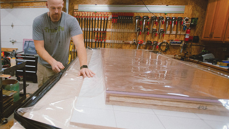
Engineered materials and vacuum-press laminations prevent warping and keep a tall, flush-panel door from being excessively heavy.
Featured Video
SawStop's Portable Tablesaw is Bigger and Better Than BeforeHighlights
"I have learned so much thanks to the searchable articles on the FHB website. I can confidently say that I expect to be a life-long subscriber." - M.K.
Fine Homebuilding Magazine
- Home Group
- Antique Trader
- Arts & Crafts Homes
- Bank Note Reporter
- Cabin Life
- Cuisine at Home
- Fine Gardening
- Fine Woodworking
- Green Building Advisor
- Garden Gate
- Horticulture
- Keep Craft Alive
- Log Home Living
- Military Trader/Vehicles
- Numismatic News
- Numismaster
- Old Cars Weekly
- Old House Journal
- Period Homes
- Popular Woodworking
- Script
- ShopNotes
- Sports Collectors Digest
- Threads
- Timber Home Living
- Traditional Building
- Woodsmith
- World Coin News
- Writer's Digest




Replies
I would just wire a #12 to
I would put a small breaker box at the outlet with 2 20a circuit breakers and hard wire the pump. I don't like using gfci on motors, and I don't like plugs on pumps. There is too little information in your question for a really good answer.
I'm assuming this is a 120v circuit. If it's a 240v there are other considerations.
You can do as you suggest -- the short length of #12 will not seriously increase voltage drop. And I see nothing wrong with using 2 #12s -- it's hardly a "parallel circuit" when the length of the run is a few inches. (Of course, I'm speaking based purely on the physics of it -- an inspector might have something else to say about these points.)
A bit more troublesome is the plug and socket. This is the weak link in such setups, and a traditional 3-prong plug is apt to develop contact resistance, overheat, and destoy the socket (and possibly damage the pump). At the very least make sure the plug is somehow mechanically secured in the socket and well protected from weather.
My second take on this is to run 2 circuits. At 150 feet, #12 is sufficient to run the pump, #10 would be better, #8 is excessive in my opinion. So, I think 2 circuits both #10 or #12 would be better. I'm assuming they are going to be burried so it's no real work to lay tyo circuits in the trench.
You can pigtail a short #12 on the #8. That will not affect the voltage drop.
He said he wanted the outlet for other uses. The pump takes 19 amps on startup. I calculate 5% voltage drop at 19 amps on #10 wire .9 power factor. #8 wire with 30 amps will have a hair over 5% voltage drop. So you cant have much more than a 10 amp load when the pump kicks on. I would rather have 2 circuits in #10. That would supply a full load on the outlet when the pump starts. To each his own.
You do not have to size the circuit for start current, only for 125% of full load amps.
Obviously you still have to be anble to start the motor but you don't have to go nuts.
What sized motor are we talking about here?
The original poster didn't say what motor he had, or if it's 220v. But I already said it would work on #12, he is planning on #8.
The point is the 150 foot run. At 19 amps startup there would be a voltage drop of 9 volts on #12 and 5.7 volts on #10, but only 3.6 volts on #8. The only real argument against using #8 is that it's pretty pricy, more than twice as much as #12. In that regard one would be tempted to use #10, which is only 30-50% more expensive than #12.
clarification
Thanks for all the advice. The pump has a 1.5 hp motor that runs on 110V. The choice of runing #8 was 'dictated' by the manufacturer due to the long run. I should have also explained that the other items I'd power on the circuit wouldn't be used concurrently with the pump in use...primarily a deicer used during the winter, but also misc pier-side uses. Thanks again, the information provided by all was a great help.
Manufacturers make unreasonable recommendations about wire size. That would run fine on #12 and #10 will be plenty. If you are really worrird, tap the motor 240v and run it that way..
Bear in mind that if you upsize the ungrounded conductors you also need to upsize the ground proportionally.
If you use #8, the ground needs to be #8. You won't find that in a normal cable. It will need to be wire in pipe.
250.122(B) Increased in Size. Where ungrounded conductors are increased in size, equipment grounding conductors, where installed, shall be increased in size proportionately according to the circular mil area of the ungrounded conductors.
Just for comparison:
I have a 1.5 HP compressor motor 450 feet away from main breaker panel. 200 ft of 8 AWg to barn, then the last 250 ft (1 roll of UF underground* ) of just 14 AWG from barn to a back lot garage. Compressor runs just fine as motor rated 208-240 V.
Everything wired directly off the 14 AWG pair. I use a surplus 240-120 isolation transformer for the 120 V loads.
It would probably be less $$ to buy a 208-240V motor than running 8 AWG, huh?.
*ta keeps youse guessing, it may just be 250 feet of old taped up and spliced OSHA reject frayed 14 AWG extension cord taped up too, eh? <G>