Discussion Forum
Discussion Forum
Up Next
Video Shorts
Featured Story
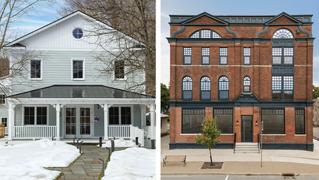
A high-performance single-family home builder shares tips from his early experience with two apartment buildings.
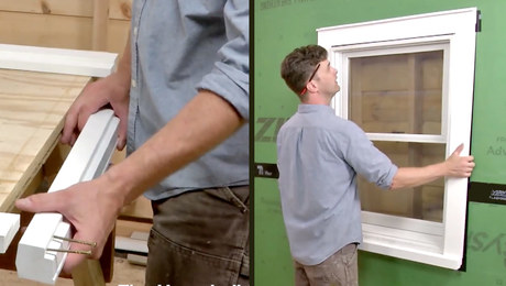
Featured Video

Highlights


"I have learned so much thanks to the searchable articles on the FHB website. I can confidently say that I expect to be a life-long subscriber." - M.K.
Fine Homebuilding Magazine


Fine Home Building
Follow
-
Fine Homebuilding
Dig into cutting-edge approaches and decades of proven solutions with total access to our experts and tradespeople.
Start Free Trial Now -
GBA Prime
Get instant access to the latest developments in green building, research, and reports from the field.
Start Free Trial Now
- Home Group
- Antique Trader
- Arts & Crafts Homes
- Bank Note Reporter
- Cabin Life
- Cuisine at Home
- Fine Gardening
- Fine Woodworking
- Green Building Advisor
- Garden Gate
- Horticulture
- Keep Craft Alive
- Log Home Living
- Military Trader/Vehicles
- Numismatic News
- Numismaster
- Old Cars Weekly
- Old House Journal
- Period Homes
- Popular Woodworking
- Script
- ShopNotes
- Sports Collectors Digest
- Threads
- Timber Home Living
- Traditional Building
- Woodsmith
- World Coin News
- Writer's Digest


Replies
Brisketbean's your man for this stuff. Joe H
Joe,
View Image
Construction Forums Online!
Sorry Joe, thought I remembered some pictures from a few years ago that BB had posted. But that drawing looks like what I was thinking of, but were there 2 or 3 of those in a hallway or entry?
Joe H
Joe,
View Image
Construction Forums Online!
Edited 2/6/2003 7:36:25 PM ET by Joe Fusco
Ken,
Have you tried different directions when framing these?
It seems to me that the direction on the left would be easier.
Joe ( Framer ),
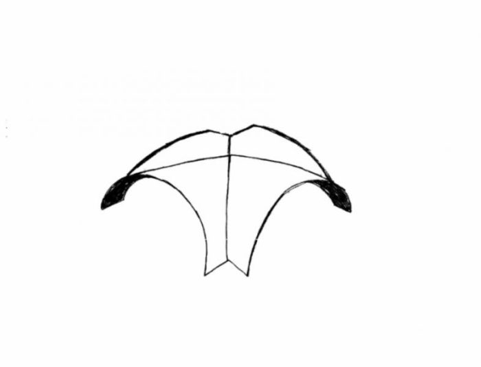
I took the time today to accurately draw the curve that would result, using the numbers from Will Holliday's "given curve from prints" ( In the attachment from your last post, from his book )
What I found, was that the resulting curve, does not look anything like what he shows it to be in his diagram. You, and others, may want to draw it out for yourselves, on a sheet of plywood, to see what you think. Personally, I just scaled it out and drew it on an ordinary sheet of printing paper. I'm attaching the shape of the curve, that, in my opinion, would result, using his numbers.
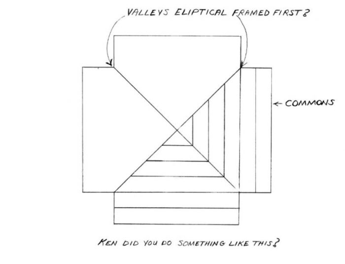
I'm also attaching a second diagram, of the curves that would result from using "Given curve from prints", as a starting point. The starting "given curve" isn't very pretty, and the results created by it, to form the other 2 curves, aren't much better.
It's not a flat radius arch, nor is it a parabola, or an ellipse, or any other of the common curves that we encounter. Quite frankly, in my opinion, these numbers were picked out of a hat, and the curve that results, is nothing that a skilled carpenter would want to use to form any portion of a groin vault.
Take a look for yourself. I am skeptical, to be quite honest, that any architect, or designer, would include numbers like he shows, on a set of prints, but I'll take Will Holladay for his word if he says that these numbers were actually shown on a set of prints. If so, I would definitely dump the architect, if indeed, he/she provided that detail.
If I've interpreted Mr Holladay's diagram incorrectly, I apoligize in advance, and I'll eat all the crow that I deserve for doing so. But until someone shows me, I'll stand by what I said here.
IMPORTANT......I'm stillworking on the process of scanning and posting so that you can get a good view of my diagrams. I hope to improve on that in the near future.
If you want to get a decent view of my drawings, RIGHT CLICK on any of the attachments first, and select, "OPEN IN A NEW WINDOW"
Edited 2/8/2003 7:55:02 PM ET by Ken Drake
layout similar to Holladay descriptin
Mike,
Post more pics! Do you have any that were shot a little closer?
View Image
Construction Forums Online!
Ken,
View Image
Construction Forums Online!<
Joe,
I appreciate your effort, your AutoCad skills, as well as your diagrams using AutoCad. But does it really have to get that confusing, and complicated, for the average carpenter?
Ken
Mike,
Thanks for posting your photo.
Could you add some information about the radii involved?
Very interesting, and nice work, but could you add something about the methods that you used to frame it, including any math involved? That's what's under discussion here.
Anthing that you add will be appreciated.
Ken
Joe,
Thanks, BTW, for resizing my drawing.
Now if i could just do that......I would had made it that size in the first place, but my software doesn't seem to know how. ( or is it me?....Yeah, I think it's me ).
Edited 2/8/2003 11:38:19 PM ET by Ken Drake
Ken,
I'm using Serif Photo Plus 5.5. It's Free.
That's how I've finally been able to post any drawings and pictures.
I'll give you the link and then you can download it.
If I could do it anyone can. ;-)
Joe Carola
http://www.freeserifsoftware.com/serif/ph/ph5/index.asp?ref=&SP=
Yesterday I posted some diagrams showing the curves that would result, if one were to use the numbers in Will Holliday's book. The curves really are not what I personally would consider acceptable for framing a groin vaulted ceiling. Definitely fire the architect that came up with those numbers. Better yet, shoot him.<G>
If I were framing it, I would start as he showed, on the 48" side, but I would simply calculate the radius of a flat circular arched barrel that would meet the requirements shown in the plans. The height of the arch is 11", and the width is 48".
The formula to calculate the radius of a circle arc, given the width and height, is,
Radius = (W² + 4H²)/8H, where W = the Width of the arch, and H = the Height of the arch. Therefore,
Radius = (48² + 4( 11² ))/8(11) =
Radius = (2304 + 484)/88
Radius = 2788/88 = 31.68", or 31 11/16"
Now, if you want to use the method described in Will Holladay's book, replace his "given curve from prints" with the circular arch. Draw layout lines to the circular arch and just measure each one. If you work accurately, you would find these measurements to be 5", 5 9/16", 7 3/8", 10 5/8", and finally, 16". ( See diagram attached)
Even though I used straight line segments to connect the dots for both ellipses, notice how smooth the curves look. In practice, you could easily "smooth out" the shapes so that they would be even more elliptical.
Would I do it that way? No. I would calculate the semi-major axis and semi-minor axis for each ellipse, and draw out each ellipse using picture framing wire as I have often demonstrated in these building forums in the past.
There certainly is nothing wrong with doing it in the manner that he suggests, and it does eliminate a lot of the math, which many are not comfortable with.
NOTE: I tried to make my file sizes smaller, but they still are coming out too large. To see the diagrams, don't LEFT click to open them, RIGHT CLICK and then select "Open in New Window" They come up nicely that way, at least on my computer.
Joe Fusco,
If you get time, would you resize them for me? Thanks in advance.
Edited 2/9/2003 10:08:19 AM ET by Ken Drake
Mike,
Thanks for the response. I would agree with you that the groin vaults are more striking if they have more radius. Ideally, you would have two intersecting full half circle barrels.
Perhaps even more eye catching, would be if you were to start with intersecting elliptical "barrels", similar to the diagram Joe Fusco showed in his post #3.
Many folks hire an artist to paint various designs on these groin ceilings, which is also very striking to look at.
I'll be framing four different groin vaults in a few weeks. I'll post some photos.
Ken
Ken,
I'll try and shrink your pictures because I need the practice and besides I taught Joe. ;-)
Thanks Joe,
That seems to be better, but I still think you get a better view by "opening in a new window"
Ken,
Are you happy now? ;-)
Joe,
Oh yes, Great Shrinker of Diagrams, I am very happy now, and will be forever grateful.
That's what I don't understand. My file sizes are smaller than yours when I posted them, but when you open mine up, they're too big. What's the ding dang deal with that?
Ken,
I don't know, I'm still getting the hang of all this but I enjoy the practice.
Did you check out the link I gave you on Serif Photo Plus 5.5.
That's what I'm using. You can do whatever you want with sizes. I still have alot of practice yet.
You said,
"Oh yes, Great Shrinker of Diagrams, I am very happy now, and will be forever grateful."
You can make it up to me if you let me Frame those 4 Groin Vaults with you. I'll point my Box Truck towards Texas. ;-)
Octagon Barrel Vault.
I would love to do one!!!!!!!
Has anyone out there ever done one?
Joe Carola
Joe just to let you know that "young fella" is on vacation will get those formulas when he returns.
P.S. how much of a drop would you be looking at on that octagon barrel?
One minor problem with framing these groin vaults that we are discussing, is what to do about beveling the ellipse so that its edges will plane in with the 2x "blocks" from the circular pattern on the wall to the edges of the ellipse.
The ellpise acts like a hip rafter in a typical hip roof. We all know how to handle that. We either "drop the hip" by removing some material from the seat cut at the birdsmouth, or we cut backing bevels on the hip. This allows the top edges of the hip rafter to plane in with the common and jack rafters in the roof.
The problem with beveling the ellipse, is that its pitch does not remain constant. In a regular 8/12 hip roof for example, the pitch of the hip remains constant at 8/16.97, or more commonly, 8/17. The pitch on the ellipse is different at every point on it. It is constantly changing as you move from point to point.
At very top of the ellipse, the pitch, or slope of the ellipse, is zero just like the top of the circles, so it would not require a bevel to plane in. But at the bottom, the bevel would be 45º, if the patterns on the 4 walls were identical full half circles. So, if you wanted to "back the ellipse", you would have to start at the top at a zero bevel and gradually increase the bevel to 45º as you reached the bottom, where it meets the circular patterns. Not easy to do, especially if you're framing a large groin vault. ( I have one to do in the current house that is 16 feet square)
A second option, would be to raise the whole elliptical pattern up a little bit, so that as the edges of the ellipse meet the circular pattern, they plane in. The problem with doing so however, is that each point on the ellipse needs to be raised up less and less as you move towards the top. At the very top of the ellipse, it doesn't need to be raised at all. So, what you have gained at the bottom in accuracy, you have lost at the top.
This problem can pretty much be eliminated, by only using one layer of plywood for the elliptical patterns. The thinner, the better. As you increase the thickness of the plywood, you increase the "bevel problem". It's very similar to the 8/17 hip rafter. If you double the hip, you have to drop it twice as much. If you bevel the doubled hip, your backing measurement must be doubled, so that you remove twice as much.
If you wished to find a method that completely eliminates this problem, other than by cutting a complicated, ever changing, bevel, you might consider this. After the ellipse is traced out on the plywood, start at the top, and eyeball a new pattern just above the ellipse, which would remove nothing at the top, but as you worked towards the bottom, slowly, increase the measurement to one half the thickness of the sheet of plywood it is traced on. In other words, for 3/4" ply, go from zero at the top, to 3/8" at the bottom. Set your saw to zero bevel and cut that line instead of the true ellipse. (See Attachment below ). In the attachment, the solid line is the true ellipse, and the dotted line would be the line to cut.
All in all though, especially if you are working with relatively "flat" groin arches, like the one demonstrated in Holladay's book, you really can ignore the problem that I am discussing if you use only one thickness of plywood. By the time it's sheet rocked or plastered, your little sins will disappear, and it will look just peachy.
Edited 2/11/2003 8:32:03 AM ET by Ken Drake
Ken,
I haven't had time to reread the section in Collin's book about beveling the ellipse. But if memory serves me correct (not a common occurrence ;-)), he says to do just the opposite as you described. He recommends cutting a pattern of the ellipse. Then trace that shape on the stock you will use for your hip. Imagine you traced out this ellipse on 4x material that was longer than you needed and wider. At the bottom of your ellipse, you would draw a 45° line diagonally across the end (where the end grain is, not along the same face you layed out the ellipse) of the 4x. Now flip the stock over so the face with the ellipse is down on the table and use the pattern you had already used and place the top directly over the top of the hip you had already layed out and the bottom you slide until it would touch the 45° line you drew. The pattern wouldn't be long enough, but you could fudge that a little. Then somehow you would cut a 45° bevel from the new offset position at the bottom to the position at the top. This requires you to have a 2 peice hip. Each with a bevel 45° to 0°. Then you could join them together. I'll post a pic of the drawing he made.
I'm not sure if this is totally correct or how to accurately cut the bevel. I'm just repeating what I understand based on George Collins book.
You'll have to right click the pic and open in a new window.
Tim,
In your post, you mentioned,
""I haven't had time to reread the section in Collin's book about beveling the ellipse. But if memory serves me correct (not a common occurrence ;-)), he says to do just the opposite as you described. ""
One reason that he says to do "just the opposite as I described", is because the page that you attached, I believe, is a desciption of the opposite situation that occurs in a groin vault.
The page which you attached is for an inside corner of a room where two quarter circles intersect, just as if you where installing 45º quarter-round crown moulding at an inside corner of a room ( like a corner where you might cope the joint). From above, it would look like a hip, and from below, it would look like a valley.
In a groin vault, just the opposite occurs.
From above, it would look like a valley, and from below, it would look like a hip.....In other words Tim, it would be very similar to what you would do if you wished to bevel the bottom side of a valley rafter for a vaulted ceiling inside the house.
For a regular valley rafter, you would cut backing bevels on the bottom side, in an identical manner that you would cut the bevels on the regular hips on the top side of the roof.
Please do reread the material and let me know if you agree or disagree.
Ken
Ken,
I don't disagree with you. I just wasn't specific in conveying what I was thinking. I used the wrong words. What you described is pretty much the same thing he wrote. What I should have written, was that George Collins recommends cutting the bevel from 45° to 0°, assuming a 90° corner. What I disagreed with you about was the bevel setting on the saw. I apologize if I sounded flippant. Like I said before, I probably have this wrong.
I still haven't had time to reread the material from Collin's book. I have a very busy night. Let me know what you think about the bevel starting at 45° and diminishing to 0° at the top. I can't really figure out how to cut that. The only thing I can come up with, and Joe Fusco suggested it about a year ago to me, but I didn't realize how to make it work, is to use a 45° chamfer bit in a router and use the pattern as a guide to cut the bevel. You would place the pattern the way you desribed, but use the router bit to go from 45° to 0. You would have to do this on both sides of the stock if you use a single piece. I'm probably wrong on this too, but I think when you do this to both sides, it would work. This assumes that the 45° is correct.
Tell me what you think. The only other thing I could think of is to set a jigsaw to the bevel and follow your method.
Tim,
You can probaly use a belt sander.
When I did those arched bays I used my circular saw. I just kept riding the blade down the top of the hip until it planed in. But you have to be pretty comfortable with your saw. I am but I don't recommend that to everyone. That was the top of a hip so it didn't have to be perfect for sheetrock so I woudn't use a saw for this situation.
Being that the ellipse goes from 0-45° . if you mark it like Ken's drawing you would probably have more control with a belt sander then a router.
Joe Carola
Tim, Joe,
If you use only one layer of say 5/8" or 3/4" plywood, I really don't think you need to bevel. Can't the sheet rock "float" for 3/8"? Certainly it can. Remember, the blocks that connect the circular pattern to the elliptical pattern are fairly closely spaced. That helps alot with fastening the sheetrock, or setting up for plaster.
A belt sander, or perhaps a small, easy to handle circular grinder like Dewalt makes, might be the way to go, if you absolutety couldn't stop yourself from creating the bevels.
ken...
obviously you guys are achieving great results.. but you seem to be going to great lengths to get there
don't a lot of these problems become moot if you change the medium from drywall to three coat plaster over expanded metal mesh ?
maybe where some of you guys live you don't have access to plasterers.. but it seems that you spend a lot of time fairing in the substrate and gypsum that could be done a lot easier with mesh... then anyone handy with stucco or concrete pool finishing could make it look great.
are we talking about olde dawgs here ?Mike Smith Rhode Island : Design / Build / Repair / Restore
Hi Mike,
I'd like to respond to your comment.
""ken...
obviously you guys are achieving great results.. but you seem to be going to great lengths to get there""
Actually, if you read what I've been posting, you'll see that I don't recommend beveling the elliptical intersections. As I've pointed out, even if the groin vault framing is off a little, all those little sins will disappear when the sheetrock guys or plasterers show up. If they are good at what they're doing, the end reulst will look good.
Other than that, no, I wouldn't say that I'm going to great lengths to "get there"
I take a straight forward approach to these groin vaults. Cut the circular arc patterns and nail them up. Determinine the shape of the intersecting ellipse, cut 2, and nail them into the intersections. Add some blocks for the rockers or plasterers and move on.
This thread got stretched out a bit, both here and at JLC, because of the poor presentation in Will Holladay's book on this subject. I, personally, don't use the method that he shows, but I felt that I needed to point out that the curves that he incorporated into his presentation, were poorly conceived of. His "given curve", as well as the curves that result from it, don't belong in anyone's groin vault, in my opinion.
What is your approach, if I may ask, to framing a groin vault?
Ever see AJ post any more?
ken.. i'm still waiting for the right customer to do a groin vault...
but if i get one... i'd lay it out in cad.. transfer it to plywood.. nail it up and bring in the plasterers..
my real question is not the arc, ellipses or the layout ... it is the use of gypsum board for the final surface... the guys that post their pics here of vaults all seem to use drywall... because that's what they do...
but i could get those results with plaster a lot easier and i'm not a plasterer.... i just like to play around with it... and i do know that most of the trowel trades .. like palster and stucco.. could knock those things out over a mesh base pretty quick..
if i find my camera.. i'll post some pics of arched ceilings i've done for myself..
so.. i'm certainly not criticizing... i'm drooling over the results.. but scratching my head..Mike Smith Rhode Island : Design / Build / Repair / Restore
Mike,
Down here in South Texas, there are more good stucco and plaster guys than there are pickup trucks. And believe me, our per capita pickup truck ratio is extremely high, perhaps the highest in the country, or even the world. You're not really considered a true Texan down in these parts, unless you own at least one pickup truck, and preferably, a cowboy hat or two, and please, don't forget the boots to go with it.
Anyway, I agree with you completely on this. Finishing a groin vault is a plasterer's job, not a sheet rocker's job. Many of these groin vaults are built in small rooms and hallways with steep curvatures, and to me, that translates to plaster, not sheetrock.
I do have one groin vault in this house we're framing now, in a room that is 16 feet square, and is a relatively "flat" groin will little curvature, and covers the entire ceiling. Two layers of 3/8 sheetrock might be the easiest way to go with that one, but in general, like the underside of an exposed circular stairway, plaster is probably the better choice. But I don't make those choices, and I'm not very good at either application, so what happens, happens.
here's my arched ceilings... when i built my train room.. i wanted no corners.. either on the wall , or at the ceiling line.. so the horizon could be seamless..
i laid out my curves for the walls... i guess the radius is about 5'.. and the arch at the approach to the ceiling which is not a true arch .. probabaly a conical section.. then laid them out with plywood and applied expanded metal lath to the walls and expanded metal mesh to the ceiling arches..
then i made a "pool trowel" and plastered awayMike Smith Rhode Island : Design / Build / Repair / Restore
Mike,
I like the interesting little forest scenes that you made. Tell us a little more about them. Take a few more photos closer up and post them if you have time.
ken.. that's from my shameful past.. before i started playing golf in '95.. i was into HO scale RR.. those are the hills of Connecticut in the background..
the home of the greatest RR in New England.. the New Haven
the walls are all blue background sky with white clouds... dark green distant hills.. the closer hills are a lighter green with wood shaving texture..
and the vegetation is all various dried weeds...
the steamer is a J1.. the last steam to run on the New Haven
and the engineer placing it on the tracks is a 12" scale model of my hand...Mike Smith Rhode Island : Design / Build / Repair / Restore
Ken,
the groin was square, about 60"x60" (it was several years ago) with about the same radii. I started with just one side, laying out the arch on a piece of 3/4" ply. Lets say 60" wide. Then I laid out a full size reflected drawing on the floor, four sides at 60", and two diagonals through the middle. I the cut 2 ply rips the length of the diagonals by the same height as the first side arch, one gets cut in half, one goes all the way through. Then you divide the first arch side any way you like, 6" spacing worked for mine (like Holladays drawing) Then you need the same number of spaces across the diagonal, but those are farther apart (pythagorean th.) Once all ply arches were cut I tacked it together on the floor to test fit all the joists in. If everything was perfect (yeah right) I could just cut 8 sets of the same number, 4 left and 4 right and nail up. but testing on the floor gave room for the "fudge factor" I did'nt have the luxury of a web forum when I built it. so I started with a good deal of head scratchin'. But it all went well once I got started. It looked pretty impressive when it was framed, but it seemed a little boring after plaster. If I was to design one, I would definitely go wider and taller (more arch) I think that would raise the "WOW factor" after completion.
Mike