On a recent episode of TOH Classic, they used some 1/8″ steel cut down into strips to sister to some 2×8 ceiling joists. The location was the attic, which had them also restoring the original dormers and the parents decided they wanted an exercize room, weights and all, up there.
They showed how they inserted these strips and thumb-aligned the ends to visually illustrate the sag in the wood joists. They then used studs under every joist to temporarily support the sagged joists while they bolted into place the sistered steel strips.
I thought the concept Tommy Silva used was interesting. I am familiar with sistering joists with other joists, but hadn’t considered this approach. Is this a common means of handling increased attic loading in renovation or restoration projects?


Replies
Adding steel certainly is an option. I don't know how often it's done.
But some thought has to be put into it. The thickness and width of steel make a difference. But how it's fastened is probably most important of all. Use the right steel and the wrong fasteners, and you're wasting your time.
Not just attics. It's a nice way to remove sags anywhere that space is a problem. No need to raise a second floor in an old house that is just supporting more weight than ever planned for many more years than expected. Lots of old homes constructed with full 2x8s that worked fine for 100 years with little furniture and such. After the addition of indoor plumbing and the 3dr layer of flooring they become overloaded and pulling the ceiling down and sistering steel is much easier than fighting deminsion lumber into place. Steel can also deal with plumbing and other notches much better than wood.
I think they illustrated the problem when they had Steve thomas bring a bucket of water up into the attic and they hopped a little showing the water flying around. Its fine if it was something like a playroom, but I guess Tommy thought for weights and weight machines it wasn't enough to leave this mid-1800's home as-is.They bolted the steel into place.
They're called flinch plates in the marine industry--same nomenclature for building const. I think. Best application is between joists, beams, spars etc. In the same manner as plywood in a header.
Right, they (flinch plates) are always better when sandwiched between materials because with the absence of any flanges on the steel, it wants to buckle when loaded. The compression from the materials on either side will help to resist the buckling action. On that note, the bolting pattern is also very important.
Yes, and I think the same term is used in the automotive and truck industry.
So, is sistering a 1/8" thick plate of steel to 2x8 joists and bolting them into place post sag-removal deemed an accepted practice? I've seen where they were sandwiched, but this was more like a toast-style implementation.
So long as the bolt pattern keeps the steel from buckling away from the wood, it should be fine. The "open face" sandwich may need more bolts.
-- J.S.
It would also be wise to install a reinforcing plate that spans as much of the length of the beam as possible. Especially avoid any steel that does not extend a considerable distance past the highest stress areas of the beam. Generally considered the center third. Complete coverage of the beam by the steel is ideal.Be aware of the weight of the added steel. If the beam has marginally supported presently adding the weight of the steel can tip the balance the wrong way. And if the 'sagging' is actually a problem of the beam not being properly supported it will likely make the situation only worse so getting a handle on the real issue is vital.
'nother way to look at it is (if it is bolted like John advised) that sistering (as in to a 2x8 #2 SYP at 550 psi design value joist) a steel1/8" by 7-1/4" piece of 20 ksi design value A36 steel is equivalent to or about 10% more strength than sistering a 2x8 joist of 1500 psi select structrual Doug Fir to the syp joist.
However, deflection is a different set of equations, the flich addition only stiffens the joist by 30%, the 2nd wood 2x8 decreases deflection by 100%. That is an additional reason the flich is like somebody else already said, a waste of both steel and wood.
> the flich is like somebody else already said, a waste of both steel and wood.
Sometimes there could be special cases where it's a reasonable thing to do. Like where you have room for the 1/8" thick steel, but not the 1 1/2" wood. Usually retrofit situations. Perhaps it does get overused, though I haven't seen a whole lot of flitch beams.
Do you put steel both top and bottom on your wood beams? How do they compare with w-series steel?
-- J.S.
I've never seen a flitch beam except in FHB articles, John!
There are only a few cases I have resorted to the steel approach, and since it has always been on an existing floor or header, it has always been on just the bottom. If I had access to the top, I'd go to the scrap yard and find a H or I beam.
What the theory of built up beams (for strength, deflection is a more complicated animal) says is that if you put steel on the top and bottom it is exactly like an H beam with the flanges what the added steel is and the web the thickness of the wood times the wood lateral shear strength divided by the shear strength of steel (e.g. 5.25" of 950 psi shear wood equivalent to 1/4" of steel). Adding just steel to the bottom makes a similar "T" beam out of the wood steel combo, so you need to know how to calc. the section modulus of a T beam plus figuring the lateral shear to know how many bolts you need (A LOT).
Believe it or not, I learned the technique in the late '40s, but not how to do the calculations till near 20 years later. Pop worked for the railroad, and he got one of the bridge designers to tell him how to reinforce the biggest beam in our house when Pop dug out the basement. Actually in that case he bolted a U channel to the bottom as that was a free piece of steel from an old railroad bridge, plus old lag bolts.
It was Deja Vue about 10 years ago when Pop and I went to the scrapyard to get a 20 ft piece of 4" by 1/4' plate 14 ft long. Brother had bought a house with a termite damaged beam that would have been a bear to replace. Remember pop commenting on it sure being easier to put in all them lag bolts overhead with an air impact wrench than by hand!
PS: Boss, if you are ever in Spfld again when I'm there again, I'll show you that first built up beam I ever 'helped' with, its the house Mom still lives in.
Edited 1/13/2006 7:33 pm ET by junkhound
Nuke,
It was an old school practice (as others have mentioned) but I think you may have trouble getting a local building inspector to accept it these days without a PE stamp. Modern engineered lumber makes it obsolete except for special circumstances (like Junkhound's photo)....that's not a mistake, it's rustic
Much more efficient to put the entire piece of steel in tension.. much more efficient use of steel than flitch.
Like Boss said, lotta attention to bolting and end of beam lateral shear.
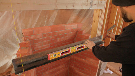
The pix shows a 1/8" by 6" wide steel plate bolted to the BOTTOM of a 6 by 14 gluelam to double its strength.
View Image
Edited 1/10/2006 12:29 pm ET by junkhound
Junkhound has it right. It is a flitch plate. Flinch is for dropping on toes....that's not a mistake, it's rustic
You're right my slip
"Junkhound has it right. It is a flitch plate. Flinch is for dropping on toes."
But I still wrap mine with duck tape <g>
Edited 1/10/2006 2:42 pm ET by Boats234
I would think that a flitch plate would use less steel & fewer bolts than what you show. Also, a flitch plate would help stiffen the upper edge of the beam, helping it to resist compression.
The deal on beams is that you need resistance to tension the most along the extreme bottom edge, and resistance to compression the most along the extreme top edge. The stuff in between is mainly just to keep the top and bottom where they belong. That's why the "w" series of steel beams have an "I" shaped cross section. The flanges resist tension and compression, the web keeps the flanges where they're needed.
What Mr. Flitch came up with was to sister or sandwich a vertical steel plate with some wood. Steel is a bunch stronger than wood, so this combination can make a stronger beam in less space than you can get with wood. There's as much steel in the middle as in the top and bottom, so in that sense, it's an inefficient use of steel. But often it's good enough.
As the Russian saying goes, "Better is the enemy of good enough." Junkhound and the guy with the rebar and epoxy have a better idea. Since the weakest property of wood is its resistance to tension, they both put steel where they need to resist tension, at the bottom. Junkhound, IIRC, also puts steel on the top of his wood beams, making them more like steel "I" beams, but with wood instead of a thin steel web.
The big thing to watch out for with either of these assembled beam designs is that the wood and steel have to be absolutely firmly and permanently attached. Let them slip just a little, and you basically have just the strength of the wood alone.
-- J.S.
John, you were doing real fine there, explaining everything very well, but you should have quit while you were ahead.
"Since the weakest property of wood is its resistance to tension"
Look up the tensile strength and compressive strength of any wood species used in construction and let me know if you want to change that statement.
Now for the 1576th time: in construction, strength is rarely the issue. Beams are rarely so undersized as to actually break. It's the deflection that is the issue. Modulus of elasticity. In construction, a wood beam becomes "insufficient" long before it breaks. The whole point of engineered wood beams is to make them stiffer, not to improve the ultimate (breaking) strength. On the other hand, if you're making a wood airplane wing spar (usually sitka spruce), lots of deflection is quite acceptable and you do worry about ultimate strength.
DG/Builder
"Look up the tensile strength and compressive strength of any wood species used in construction and let me know if you want to change that statement."
How about looking at 2X12 #2 SYP. The design value for tension is 550 PSI. The design value for compression is 1450.
So the compression value is more than 2.5 times as high as the tension value.
"in construction, strength is rarely the issue."
After doing design work for 20+ years, I'd say strength is the issue about 90% of the time.
You may be confused by the fact that an underdesigned beam tend to sag badly. If the beam isn't strong enough it starts to bend. Wood gives a lot before it breaks.
But that doesn't mean that deflection is the primary concern in designing wood beams.
If you're not part of the solution, there's good money to be made in prolonging the problem.
Hey Ron, you would know this as I've forgotten,
what is the term for a truss failure when the nail plate pulls a chunk of wood out of the side of a member?
That would seem to be a classic perpendicular to grain tension failure totally unrelated to truss deflection.
"What is the term for a truss failure when the nail plate pulls a chunk of wood out of the side of a member? "
I've heard it called "chunking" or "chunk-out". But I don't think there's really a specific term for it. That's just how people refer to it.
I don't think it's typically related to tension parallel to the grain, but rather perpendicular. It used to pop up now and then with a large sized bottom chord with a small plate connecting a web to it. But new design rules require certain depths of plates in order to prevent this problem.
The best way to have a quiche for dinner is to make it up and put it in the oven to bake at 325 degrees. Meanwhile, get out a large T-bone, grill it, and when it's done, eat it.
As for the quiche, continue to let it bake, but otherwise ignore it.
BossHog:
Quote: "How about looking at 2X12 #2 SYP. The design value for tension is 550 PSI. The design value for compression is 1450. So the compression value is more than 2.5 times as high as the tension value."
Yes, and that DOES NOT mean the wood is stronger in compression. The design value is size and application-specific. That's why you said 2x12. And that is for a specific use. Both tensile and compressive strength are intrinsic properties of the wood and do not depend on the size or application. They are well in excess of the design value. For SYP they are in the range of 9-12ksi tensile and 3-5ksi compressive.
Design values are normally chosen at a small fraction of the ultimate strengths in order to give an acceptable deflection under the anticipated loads. For a beam (e.g. floor joist), ultimate strength is defined by the Modulus of Rupture (bending strength). But the design value is much, much smaller because of deflection, which is a function of the Modulus of Elasticity (rigidity). That's why we have engineered wood beams. They are much more rigid for the same ultimate strength.
Quote: "After doing design work for 20+ years"
Well, it's never too late to start consulting a structural engineer...:)
DG/Builder
I don't know where you're getting your information, but it's way out of whack. The design values I quotes are from back when they did full size testing back around 1991. They are the current accepted design values. Every lumber species I know of has higher compression values than tension. No exceptions. I think YOU are the one who needs to consult an engineer.
Mediocrity: It takes a lot less time and most people won't notice the difference until it's too late.
BossHog,
Clearly you don't grasp the difference between design values and the strength of wood. That's the fist thing to work on.
My information comes from the bible of wood:
Forest Products Laboratory. 1999. Wood handbook—Wood as an engineering material. Gen. Tech. Rep. FPL–GTR–113. Madison, WI: U.S. Department of Agriculture, Forest Service, Forest Products Laboratory. 463 p.
Get it, read it and learn. Then still use an engineer. Not being rude, but you are insufficiently informed to design wood structures.
I do consult an engineer. One of the greatest virtues in any trade is to recognize one's limitations and stick to one's day job. I don't do freelance brain surgery either :)
DG/Builder
Seems to me you're the most dangerous kind of person - Someone who knows a little about something and thinks they're an expert. You show a complete lack of ability in structural design and then try to tell me that I don't know what I'm talking about?I see you've only been a member for a week. I'll cut you some slack since you haven't been around long enough to know me or have a clue what I'm talking about. Structural design is what I do for a living. Back off and learn for a while before you come in here insulting regulars on the board.
A smart person will learn a lot more from an idiot than an idiot will ever learn from a smart person
Wow. You just never know what direction one of these threads is going to go. Thanks, Ron. I see you handled this one thoroughly before I got back here. ;-)
-- J.S.
BossHog,
You never answered the question. What are the tensile and compressive strengths of wood (any species you want, green, 12% or anything you choose) and which one is greater? Not design value for a 2x12 in your particular, specific application. And provide your reference.
When you first jumped in, we were talking strength of wood, not design values. Read the post. It's still there.
DG/Builder
What I gave you WERE the design values for tension and compression in wood. (In that particular size, grade, and species)So I have no idea what you're getting at.
We weren't selling cigarettes, we were selling an image. An image to young boys. [rock-climber David Gurlitz on his Winston ads]
Thanks for the info on the chunking Boss, have heard of that failure mechanism, bet never have observed it directely. You are correct, I should have said perpendicular to the grain. Thanks for ref. info on the current values of #2 allowables also.
Anyone who doubts Boss should tell me how the sticks in the attached pictures attached failed in compression, sure look like tension failures to me too.
BTW, take a look at something like http://www.srs.fs.usda.gov/pubs/4701/383.pdfm for some really esoteric discussions on wood fracture.
FWIW: Page 721, Marks Mechanical Engineering Handbook, (1930 copy for interest) Does show, for Shagbark hickory, one of the highest tensile strength woods and one of the toughest, that:. <!----><!----><!---->
Fiber stress at elastic limit, (tension) = 12400 psi<!----><!---->
Compression parallel to grain = 10420 psi<!----><!---->
So according to the simplistic ultimate strength theory, a stick of this should have a compression failure first. <!----><!---->
However, simple observation shows tensile failure. (see pix) Hmmmm, is there a factor other than simple ultimate or elastic limit compressive strength going on.
HO ho ho, there seems to be another measurement, other than ultimate, that is similar to Boss’s (correct) numbers, e.g. for SYP (longleaf) my old book says 3691 tension to elastic limit, 3480 compression to elastic limit: BUT, there is also a ‘crushing strength to max bending load’ number of 4800 for compression. (see web site above for partial microbiological effects that make this so). A lot of factors went into the correct numbers for working strength that Boss quoted, not even considering knots and defects. Nor considering lateral shear which is vry important in assembling built up beams.
Sorry for the big pix, that is what my camera was set at.
BTW2, there is still another failure mechanism on the maple (the grain was not straight, failed in perpendicular to grain tension.
You just gotta post them big pics, don't ya ??? I downloaded them anyway, since it was you who posted 'em. BTW - Was the vice you used in that picture ASTM appproved ???(-:I don't know how they came up with the impressive tension/compression figures you mentioned. But I suspect that were small samples of clear lumber. But since those values are from 1939 they really don't apply now. And they were ultimate values - Not typical design values.Back then lumber was tested using the small, clear samples I mentioned. They apparently didn't have equipment to do testing of full sized 2X lumber. Then they used formulas to try to predict how larger pieces of lumber would act. Any size of lumber in a particular grade and species had the same design values. ie: All SYP #2 had the same design value for tension, compression, etc. Then in the late 1980s/early 1990s (don't recall exactly) they did testing on full sized pieces of lumber. And they changed design values quite a bit in some cases. In particular, they dramatically dropped tension values on larger lumber, like 2X12. Part of the reason for that was that lumber has knots in it. Knots kill tension values. And now every different size within a specific grade/species has it's own design values. I could ramble on about this stuff, but don't want to put everyone to sleep...
These tag lines are from a colletion of my favorite jokes. They're really funny, if you have low standards
Junkhound -An extra "m" managed to attach itself to the URL you gave. For anyone who didn't figure it out, this is the (slightly) corrected reference:http://www.srs.fs.usda.gov/pubs/4701/383.pdfSince all of my references are packed away, can someone give me the similar design figures for tension and compression for mild steel beams?(I've done a Google search but haven't yet hit on the magic search terms)
I think I replied to you in ;my reply to Boss
- note of caution: anybody who has disputed Boss Hog on truss detail in the past has been proven wrong (myself included)
Ohhh Maannn.Why did you have to go all reasonable, rational and pull out Hogg's ranking. I was quite enjoying the boys going after each other in a vigorous sliderule fight. And with barbed words no less."It's years since we've heard the clash of sword against shield...
...the clamour of armoured knights crashing to the ground...
...the spurt of blood as the dagger is thrust into unprotected groin."From the movie "Jabberwocky" by Terry GilliamReferenced through: http://www.script-o-rama.com/movie_scripts/j/jabberwocky-script-transcript-terry-gilliam.html
Did you dig out this thread and take a look after the reference to you* in the plumbing thread??
*Looking forward to your responses to any such irrational challenges - maybe some people do not have a clue?
Yes Junkhound, you did acknowledge the correct strength numbers. Thank you. Perhaps you can share your source with BossHog, as he inquired as to where I got them.
I don't know how you broke those sticks, but from the pictures looks like bending load. You are the one who can tell us how you did it and which side of the stick gave first. I wasn't there.
The point I made is that the strength of wood (compressive, tensile, bending or other) is not to be confused with design values, nor are the two necessarily proportional. Strength was set by nature and will stay set for a while. Design values were negotiated by humans based on their needs and wants. Apparently some respondents (no names, he he he) either failed to understand what I repeatedly wrote, or did not grasp the whole concept at all.
The design values are based on the intended application and specific size of the member. As such, they must consider the allowable deflection and other factors. That is why allowable design values are so much smaller than the ultimate strength. If you are designing a diving board, you can design it to the elastic limit (which is still short of the ultimate strength). But a joist, you may not want quite that much deflection, so you choose a design value that's more drywaller friendly...:)
BTW, i have yet to see wood used in construction fail in tensile or compressive. Most failures are either bending or column buckling. I did see a couple of shear failures last week. Not pretty.
DG/Builder
Boss is right, you know enough to be dangerous. Bending stress is made of two components: tension and compression. While grain has an impact on failure plain, it is the tensile rupture that occurs when a joist fails in bending....that's not a mistake, it's rustic
While I agree with--
"Much more efficient to put the entire piece of steel in tension.. much more efficient use of steel than flitch. "
BUT
I feel that would be more aptly applied to catenaries, post tension and vertical loads. Where you're dealing with the tensile properties of the steel compared to its buckling tendencies.
The bottom ply of your gluelam being a perforated 1/8" steel plate only comes into tension on movement or failure of the beam- provided no slippage at fastening points
Boats,
You said, correctly, I think,
"The bottom ply of your gluelam being a perforated 1/8" steel plate only comes into tension on movement or failure of the beam- provided no slippage at fastening points"
Isn't it true on the other hand that with a flitch plate beam, the wood is only loaded after the failure of the steel?
A few years ago, I read a piece in the house magazine of the Gougeon Bros, who manufacture WEST System epoxy, about a joist strenghtening technique. The writer milled a (I'm guessing) 3/4" x 3/4" groove into the bottom edge of a 2 x something, laid in a 10M epoxy coated rebar and filled the groove with thickened epoxy. This was done upside down on the bench and then the thing was installed and loaded.
I know that would increase the capacity of a beam but I don't know how to figure how much without load testing it.
Ron
"Isn't it true on the other hand that with a flitch plate beam, the wood is only loaded after the failure of the steel?"
Pretty Much
The only place I've ever used or seen one used is to repair/ beef up an overloaded or damaged condition. The load has always been more of an eyeball estimate then an engineered one. If an engineered repair was required, I guarantee you it would be a total rip out /start from scratch solution before anybody would put a stamp on it. And rightly so due to liability issues and such.
I have seen many architects insist on a plate system for post and beam constrution-- but only to reinforce the joints--not as a splicing or sistering application
But if it's your house, boat or barn--knock yourself out.
This is really facinating to me. I have a space that is 18" high by 20' 6" wide... that 18" rises to about 4' at the peak of the roof. I'm working out how best to frame this for storage.
12" is a great minimum height - good for small heavy boxes like books or auto parts. But using conventional techniques quickly eats away that 12" minimum next to the wall where it would be best to place the heaviest items. Most joist products start at 7.25" to 9.25"
Unfortunatly, since the space is over 20', regular steel beams need to be lengthened, adding alot of work for just 6 more inches (ahhh, what we all could do with 6 more inches ;).
But, here is something I've been tossing around based on this rebar reinforcement concept:
1. Cut a series of 2x6 beams (16" or 24" OC) using 22' stock
2. Route or cut a 9/16" or 5/8" wide by 3/4" deep channel down the center of the thin face of each beam.
3. Where the bottom of the 2x6 will rest on the rim board, drill a 1/2" hole at an inch deep so the bottom edge of the hole is on the bottm edge of where the beam will be.
4. Place in these holes a length of 1/2" rebar that is 2" longer than the 2x6 beams you've cut. Rebar comes in 20' length, so a little welding is needed.
5. Place the 2x6 beams, channel up, under those bars so that the top of the channel just covers the top of the rebar where it meets the wall. There will be a slight sag throughout the length of the rod so that the center rests on the bottom of the 3/4" deep channel.
6. Mix and pour the epoxy into the channels. Some tape on the edges of the beams might be needed to keep it from running out the end and down the wall.
7. After the epoxy has fully cured, remove temporary beam supports. Roll the beam over 180 degrees, so that the channel runs along the bottom. Use standard face hangers like an HU26 to keep it oriented correctly, and block as usual.
View Image
This should result in a reinforced beam that uses the strength of the steel thoughout the compression areas, even into the supporting rim for shear. Topping it with 10' or longer OSB in parallel fastened every 6" in the field in the center of the span will give added compressive strength. The slight upward bow of the rod will give added reinforcement across the length of the beam.Rebuilding my home in Cypress, CA
Also a CRX fanatic!
About $100 a gallon for West System epoxy. Just for general info
Thanks, that's about what I saw too ($130 for a whole kit). By my calcs, 1 gallon should fill over 5 of those slots - perfect for a 10' area (24" OC, the 6th is the bolted to the existing front wall).Rebuilding my home in Cypress, CA
Also a CRX fanatic!
Paul,
There must be an easier way! As I recall, the writer of the piece in "Epoxyworks"
http://www.epoxyworks.com/17/beam.html
had space limitations that you don't have.
You could probably add some serious reinforcement to 2 x 6 joists by doubling them, sandwiching a length of rebar in the middle. If you welded a cross plate at one end of the rebar and a threaded rod at the other, you could put a spacer at the top of the beam assembly and pre-tension the bar at the bottom edge of the sandwich. No milling, no expensive epoxy, no sticky mess, hardly any more welding than you were considering in the first place.
That isn't very much depth for that much span, though.
Ron
If depth is the problem and you're worried about wasting I beam for your greater than 20' span, use a piece of box tubing (hollow structural steel). It's available in 24' and 48' lengths. Although the weight per foot will be more, you can generally find one with more stiffness for a given depth than is available with a wide flange I beam.
The slight upward bow of the rod will give added reinforcement across the length of the beam.
Sorry, it does not work that way, the crown in your drawing actually decreases the strength slightly. If you go the epoxy route, best to have the rebar only 1/2 way into the wood, you want the steel as far from the structural centerline of the 2x6 as possible and still get enough epoxy to provide the lateral shear, which may mean it does have to be fully embedded in epoxy.
There is another option you may want to consider for your special case, and that is an inverted cable truss. Add a 2x6 block (or however far down on the ceiling is convienient) at the bottom of the center of the beam and bolt some steel anchors to the ends of the 2x6. With a turnbuckle , tension a cable over the block tieing into the end brackets. You now have a classic inverted truss, the 2x6 is in compression only for a load at the center of the truss, 2x6 stresses get more complicated as you load the floor above. For a 2x6, you now need to watchout for column bending of the 2x6 also, but the floor should take care of that. Boss probably can just plug those numbers into his truss program. Insurance companies in ranch or farming areas used to (maybe still do) stock kits to take the sag out of barn beams withthe cable fix.
"Boss probably can just plug those numbers into his truss program."
I don't think so Tim.
Truss programs are only made for designing wood trusses. You can play games with them to some degree. But they're not particularly flexible.
Heidi Fleiss was sentenced to prison on pandering charges. She says she is appealing.
I don't think so, but did you see some of her girls?
Well, that arched rebar I was thinking would push into the walls under compression, instead of pulling away. Kind of like an arched bridge.
But now you and Ron have given me two even better ideas. Pretensioning the beams is brilliant! I couldn't figure out how to do it myself.
I'll also have to look into Moltenmetals idea of square tube.Rebuilding my home in Cypress, CA
Also a CRX fanatic!
Paul,To visualize the way to use steel in tension to strengthen/stiffen wood, just look at the truss rods on a wooden stepladder. They go under a small block at midspan so the step is preloaded upwards to counteract sag. I once used this principle to make a 4 foot flush beam out of blocking and all-thread, while letting the long joists it supported pass through uncut.Bill
Wow Junkhound, you know all of the old school tricks. Most engineers would look at you like you were nuts for a wile vefore realizing how simple that fix is....that's not a mistake, it's rustic
That sounds like what we have all over the place on the top and bottom edges of garage door slabs. Usually it's done with 1/4" steel rod as the tension member, and a center standoff that pushes it out about 4". It keeps the door from sagging when it's open.
-- J.S.
A little bit late to the party, but one more comment about this. Welding rebar is a very iffy proposition. Rebar is specified by its cold properties, and the mill is free to do whatever heat treating they want to get it to that strength. Since a lot of rebar is made from scrap that varies from melt to melt, the composition of your rebar and the heat treat used can vary widely. If you go weld something that's heat treated, the heat cool cycle will completely undo the heat treat, and the metal in the heat affected zone can be extremely brittle, and yield far lower strength than the original spec. I'd also be very concerned about how many fatigue cycles it would survive. Some people swear by field heat treating with a torch, but that requires skill, care, and a good guess about the actual alloy you are working with.I used to make things out of welded rebar, but one scary failure (not a weld failure but next to it) has taught me to be very careful. I'd second the other folks recommendation to use some sort of mild steel stock or cable. You will get a much more predictable result.
Mark,
Very good point about rebar. I have cut a lot of rebar with shears and have noticed big differences in the properties of the metal between one piece and anpother and sometimes between different ends of the same piece.
Ron
The steel yard I bought my rebar from sells only "weldable" rebar and gives mill certs to demonstrate the properties. Builder's supply yards wouldn't offer that consistent quality though- rebar is a real bottom-feeders market for steel, and the cheapest stuff can be absolutely terrible material to work with. Variable properties and chemistry are the rule rather than the exception. I agree with the other poster- you'd have much more luck with mild steel round- or flatbar.
Thanks for the heads up! Looks like I've got to make another trip to the steel yard to do some imagineering.Rebuilding my home in Cypress, CA
Also a CRX fanatic!
Well, I just got back from the steel yard. The 6"x2"x.125" wall rectangle tube looks like the best candidate. Comes out to $400 for 3 beams, I'd have to run mini joists between them which adds more.
The other option I am exploring is that epoxy embedded joist. I figure the price works out like this:
2x6x22' $19 + .5"x20' rebar $5 + Epoxy $10 (roughly) = about $40 per beam
While the actual length I am spanning is about 20'6", I figure the rebar be the tension segment across the area where it is important, while the ends are mostly supporting shear.
I just picked up a board and rebar to test this whole thing out. Right now it's air drying in the garage. If this doesn't work as planned, but is close, then I'll try it again using threaded rod in tension. I will probably end up using the Simpson SET epoxy, just because it's the only epoxy I can easily get my hands on locally.
Rebuilding my home in Cypress, CA
Also a CRX fanatic!
Edited 1/21/2006 12:12 pm ET by xxPaulCPxx
Flitch plates are a commmon aproach. But they are pretty inefficient and, if inproperly used, can actually make a beam weaker than it was originally.
The inefficiency comes about because steel and wood have different leveles of elesticity. Essentially they act seperately even though they are bolted together. The steel is far stiffer than the wood so it takes the strain while the wood is simply flexing out of the way. If and when the steel fails it would fail completely and only then the wood would take any significant portion of the load.
The only benefit that he wood offers to the steel is in lateral support and deflection. Important to prevent buckling of the steel but it is not the same as handling the direct load.
The way this shakes out is that when designing a flitch plate you have to design the steel to carry the complete load independent of the wood. The wood only providing support to prevent lateral deflection. A role which in many situation is largely redundant seeing as that, especially in the case of a floor joist, the floor above and ceiling below prevent lateral deflection and buckling.
Some structural engineers loosely characterize flitch plates as 'A waste of both wood and steel'.
Another consideration is that flitch plates, if they are not made long enough can cause concentrations of stress, typically worse where the steel stops and there is wood alone, which can actually weaken the structure they are intended to strengthen. The situation being made even worse because the steel is itself a substantial weight that the whole beam has to support.
All of this points toward the need for great care and the desirability to consult with an engineer when designing and installing flitch plates.
Flitch plate is it my only fix
Hope someone is looking. I have a 25 year old cedar log cabin. The ceiling over the kitchen/dining room supports an upstairs bedroom and bath. The size is 11' x 19'. The ceiling is exposed and is supported by 5 67/8" by 3" wood beams running the long way. These are notched at each bearing end in half leaving approx. 3 1/2" bearing on the outside cedar timbers. The 5 beams are approx. 40" on center. The beams are deflecting about 1/2 to 3/4" and the T&G floor above is squeaking and buckling in areas. As this area is exposed i am proposing jacking the sag out slowly a smidgen over level and to use a 3/8" fitch beam attached to the center beam on both sides and through bolting it in a zig zag manner. With all the steel painted black the area would have more of an industrial look. The ends of the flitch plates could be set on angle steel for support.
any ideas before this starts, please.
bobbob1
How 'bout this idea before you start:
Hire a qualified professional engineer to specify your retrofit framing work. This way you'll be more apt to effeciently use appropriate material in all the correct places.
Bolting patern
Does anyone know what the bolting pattern would be for sistering an 1/8* steel plate to floor joists?
Bolting patern
Does anyone know what the bolting pattern would be for sistering an 1/8* steel plate to floor joists?
Wow, U and bobbob both too lazy to read the entire thread --
SO
I AGREE with DN in this case, you 2 need to hire a professional engineer as you are obviously not capable of intellignet DIY. !
OMG, did I actually say that? Did I actually agree with DN on hiring recommendations <G>
do you have a link to the this old house clip you mentioned?