water flow dynamics and dielectric couplers
the situation:
well-water goes to a well tank.
copper tubing from well tank has a branch that goes to exterior household frost-free spigots, and bypasses the water filter and water softener systems, but can take on filtered/softened hot water via a mixing valve.
the well-water has a high mineral content (fe and magnesium or manganese).
the water temps will vary from 50 degrees f (well-water temp) to 110 degrees f (makes washing dogs/car in the winter more tolerable).
there may be a occasional grain of sand in the well-water, which may adversely affect the function of the check valve and/or ball valve.
pressures will be 40-70psi. flow will be between 0 and 12gpm.
i plan to install a stainless steel check valve and a stainless steel ball valve in the line going to the exterior spigots.
the ‘full port’ diameter of the check valve and the ball valve will be the same, either both 3/4″ or both 1″.
two issues:
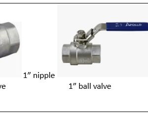
1. i can’t find 3/4″ stainless steel check valves with the proper ‘guts’ that are more suitable for for our well-water (unless i multiply the price 10 fold), but i can find the desired ‘guts’ in a 1″ stainless steel check valve. so the system would look something like the attached photo.
2. i have heard that dielectric couplers are notorious for developing leaks as the washers in them degrade. i have also heard that the galvanic properties of copper and stainless steel are close enough that some plumbers think dielectric couplers aren’t necessary (the dielectric coupler would trade one problem – galvanic corrosion – for another problem – degradation of the coupler and leaking).
see the attached diagram.
there will be a stainless steel close-quarter nipple between the check valve and the ball valve.
the check valve and ball valve will have both ends with fnpt.
if the answer to question #3 is to just stick with 3/4″ check valves and ball valve, then the 3/4″ to 1″ adapters won’t be needed.
questions:
1. between the copper tubing and the stainless steel check valve at one end, and between the copper tubing and the stainless steel ball valve at the other end, do i really need a dielectric coupler, or do you just recommend direct connection between the copper and the stainless steel? or maybe even a brass nipple intermediary?
2. it’s been 45 years since i took water flow physics in college. perhaps you can help me… what will be the flow dynamics, resistance/friction, pressure changes if i put a 3/4″ to 1″ adapter at each end of the 3/4″ copper tubing and insert a 1″ check valve and 1″ ball valve in the center section? or in my residential setting would it be insignificant?
3. or should i compromise on the quality of the poppet and seals (delrin and buna-n) on the check valve, and just get the 3/4″ check valve and 3/4″ ball valve (viton and nylon or noryl)?
any plumbing engineers out there willing to give advice?


Replies
3/4" check valve:
https://www.mcmaster.com/products/check-valves/pipe-size~3-4/body-material~stainless-steel-1/
hi ct_yankee, (i was born in ct)
thank you for taking the time to answer.
the check valves you reference use a fibroelastomer rubber (viton).
viton is less forgiving than nitrile (aka buma-n, aka nbr) seals/rings.
nitrile has a better abrasion and tear resistance than viton.
this is important, due to the occasional grain of sand that is pumped up from the 500ft deep well, and the sand may abrade the seal.
can anyone else address the issue of flow dynamics of going from 3/4" to 1" to 3/4" tubing, and the dielectric coupler/galvanic corrosion issue?
much appreciated.
I don't know about the flow question, but I would use brass couplings on each side of check valve. Should not be any galvanic problems with the brass. (I use a brass 6" nipple between copper and galvanized pipe all the time in lieu of dielectric)
And reducing 3/4 x 1 brass coupling would probably work just fine