A hip roof with a square-cut fascia contains some tricky compound angles that can trip-up even the most experienced carpenter. Especially difficult is the compound angle on the fascia at the outside corners, and the backing angle for beveling the top of the hips or valleys to plane in with the rest of the roof.
I’ve seen all kinds of explanations from proprietary construction calculators to framing square gymnastics to figure these angles, and I’ve worked them out with geometry and trigonometry. A lot of framers just guesstimate and call it good enough (and it shows in their work).
I wanted a direct, hands-on method that would allow me to figure the angles accurately without guesswork, calculators, protractors, or math tables. I wanted to be able to visualize each angle’s relationship to the big picture, to be able to set my circular saw bevel at the proper angle. I wanted something I could set down and walk away from, and pick up later and still remember what was what.
I was determined (OK, obsessed might be a more accurate term!) – I took a night class in trigonomety, just to try to get a handle on this. I went to bed thinking about it, and woke up thinking about it. And after untold hours upon hours of complicated and convoluted analyzing, sketching, figuring, head-scratching, and frustrating dead ends, I arrived upon a solution that is so simple it’s almost ridiculous!
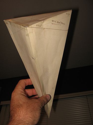
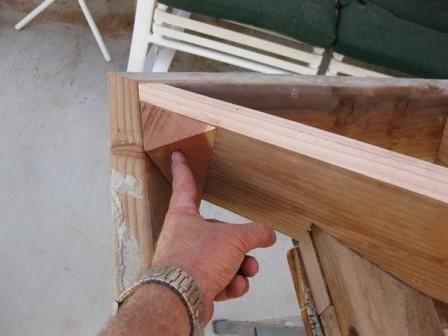
It’s made from a scrap of 4×4 (or any square chunk of wood), and it contains all the angles needed to cut a hip roof with a square-cut fascia. Once you have it in hand, you can set it on your skilsaw base and adjust the angle of your cut without even knowing or thinking about how many degrees the blade is set at.
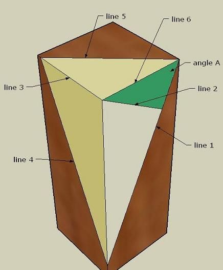
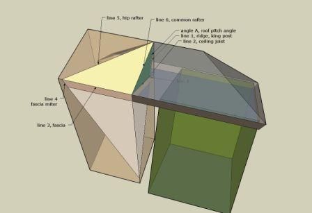
The key to the whole thing is being able to visualize how the angles in the mockup relate to the angles found in the actual roof. Look at it, and see line 6 as a common rafter, line 5 as a hip rafter, line 3 as a fascia, and line 2 as a ceiling joist. Once you grasp that, everything is a piece of cake. Well, maybe not exactly that easy, but you get the point. =)
Here’s how it works: Angle A represents the pitch of the roof. Line 2 is drawn at 90 degrees to line 1, from the corner. It represents the run of the roof. And the green side of line 1 represents the rise of the roof.
Line 3 is drawn at the same length as line 2. Lines 4 and 5 are drawn once the length of line 3 is determined. Line 5 represents the hip rafter, as line 6 represents the common rafter.
If you cut away the dark brown portion, the piece remaining contains all the pertinent angles, in 3D, including the fascia compound miter angles, the roof sheathing compound miter angles (which are more important when working with thicker sheathing, like 2x planking), and the backing angles for hip and valley rafters.




View Comments
Huck,
I must say this is one of the better tricks I've had the pleasure to read about! I'm pretty good at math, geometry and trigo, but this will be such a awesome time saver! Thank you so much.
Tried both the links; they both gave "Video unavailable. This video is private"