Conquering Complicated Roofs
Strategies for calculating the angles and offsets of irregular hips and valleys.
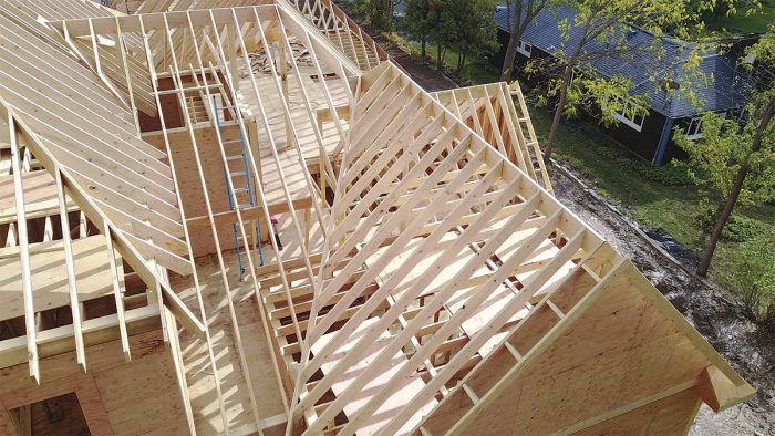
Synopsis: Roof framer Ryan Smith details his method of laying out bastard hips and valleys, which need to move off the corner to create equal and level overhangs. The calculations can be complicated; by creating a plan-view drawing on a piece of plywood, Smith outlines each step of his process to establish the overhang and locate all of the angles.
I didn’t start out with great techniques for figuring out and cutting complex roofs. On roofs with bastard hips and valleys, I used to wait until the walls were up and use stringlines and squares to determine the angles. It kind of worked, but it wasn’t perfect. After years of late nights and weekends spent inside and outside my garage tinkering with ideas and testing them out, and putting those lessons to work on real houses, I’ve learned how to figure out most things on my own. Now I can start figuring and cutting a roof before the rest of the crew has the first-floor deck finished (not that they’re slow enough for that to happen).
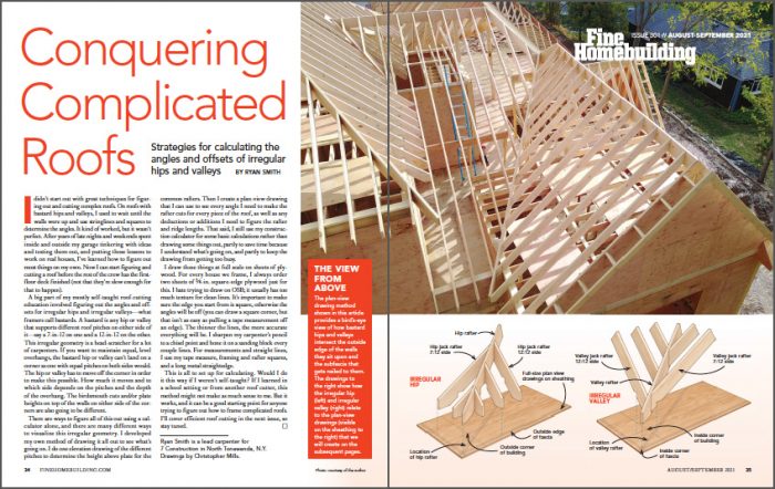
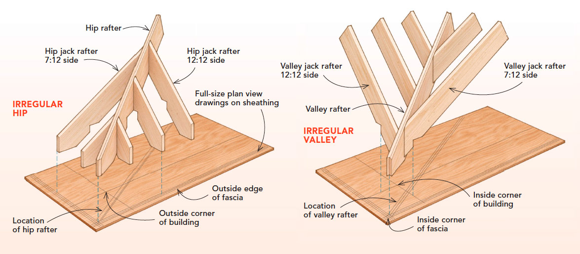
A big part of my mostly self-taught roof-cutting education involved figuring out the angles and offsets for irregular hips and irregular valleys—what framers call bastards. A bastard is any hip or valley that supports different roof pitches on either side of it—say a 7-in-12 on one and a 12-in-12 on the other. This irregular geometry is a head-scratcher for a lot of carpenters. If you want to maintain equal, level overhangs, the bastard hip or valley can’t land on a corner as one with equal pitches on both sides would. The hip or valley has to move off the corner in order to make this possible. How much it moves and to which side depends on the pitches and the depth of the overhang. The birdsmouth cuts and/or plate heights on top of the walls on either side of the corners are also going to be different.
There are ways to figure all of this out using a calculator alone, and there are many different ways to visualize this irregular geometry. I developed my own method of drawing it all out to see what’s going on. I do one elevation drawing of the different pitches to determine the height above plate for the common rafters. Then I create a plan-view drawing that I can use to see every angle I need to make the rafter cuts for every piece of the roof, as well as any deductions or additions I need to figure the rafter and ridge lengths. That said, I still use my construction calculator for some basic calculations rather than drawing some things out, partly to save time because I understand what’s going on, and partly to keep the drawing from getting too busy.
I draw these things at full scale on sheets of plywood. For every house we frame, I always order two sheets of 3⁄4-in. square-edge plywood just for this. I hate trying to draw on OSB; it usually has too much texture for clean lines. It’s important to make sure the edge you start from is square, otherwise the angles will be off (you can draw a square corner, but that isn’t as easy as pulling a tape measurement off an edge). The thinner the lines, the more accurate everything will be. I sharpen my carpenter’s pencil to a chisel point and hone it on a sanding block every couple lines. For measurements and straight lines, I use my tape measure, framing and rafter squares, and a long metal straightedge.
This is all to set up for calculating. Would I do it this way if I weren’t self-taught? If I learned in a school setting or from another roof cutter, this method might not make as much sense to me. But it works, and it can be a good starting point for anyone trying to figure out how to frame complicated roofs. I’ll cover efficient roof cutting in the next issue, so stay tuned.
| THE VIEW FROM ABOVE: The plan-view drawing method shown in this article provides a bird’s-eye view of how bastard hips and valleys intersect the outside edge of the walls they sit upon and the subfascia that gets nailed to them. The drawings below show how the irregular hip (left) and irregular valley (right) relate to the plan-view drawings (visible on the sheathing to the right) that we will create on the subsequent pages. |
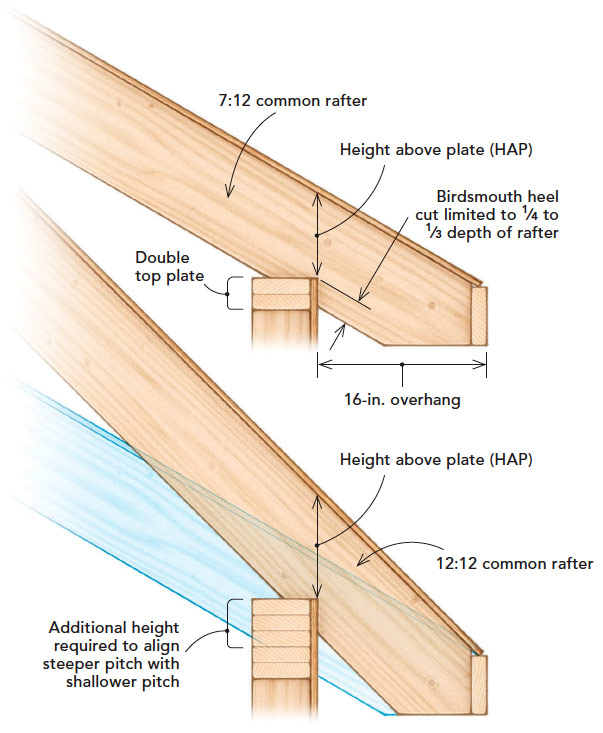 1) LAY OUT THE BIRDSMOUTHS
If you want equal and level overhangs, the different pitches on either side of a bastard require that adjustments be made to compensate for their different rises over the same run. The birdsmouth cuts, plate heights, or both will be different from one side of the corner to the other. You may have to add additional plates, a short cripple wall, or build the wall taller on the steeper side of the roof to position the rafters properly. Drawing this out makes it easier to visualize and to figure out the plate heights and the height above plate (HAP) for the birdsmouths.
Start by drawing the fascia and building line (the distance between the outside edge of the fascia and the building line is equal to the overhang), then extend the pitches back from the top center of the fascia, over and through the wall line; these lines represent the tops of the rafters. Drawing a pitch can be done by simply lining the 12-in. mark on the blade of a framing square with the top center of the fascia, marking the appropriate pitch off the square’s tongue, and connecting this mark back to the top center of the fascia. Once the lines for the tops of the rafters are drawn, measure and mark the depths of the rafters square off of them and draw lines indicating the bottoms of the rafters.
The HAP is somewhat dictated by code—there’s a maximum you’re allowed to cut into a rafter. In the International Residential Code (IRC), that max is one-quarter of the rafter material’s depth. Where I work, we’re allowed to go as deep as one-third—I’ve never been called on it, anyway. I use that requirement as a guide to establish the HAP at the back of the birdsmouth. After the rafters are drawn in, I draw the birdsmouth and the plate it sits on. From that, I can simply look at how the other rafters intersect the wall line to determine the birdsmouth cuts and additional plating or wall heights needed to support those. The top drawing shows a 7-in-12 common rafter on top of a standard wall. The bottom drawing shows that same rafter ghosted out with a 12-in-12 rafter superimposed. They start from the same point at the center of the fascia, but additional wall height is needed to support the steeper pitch.
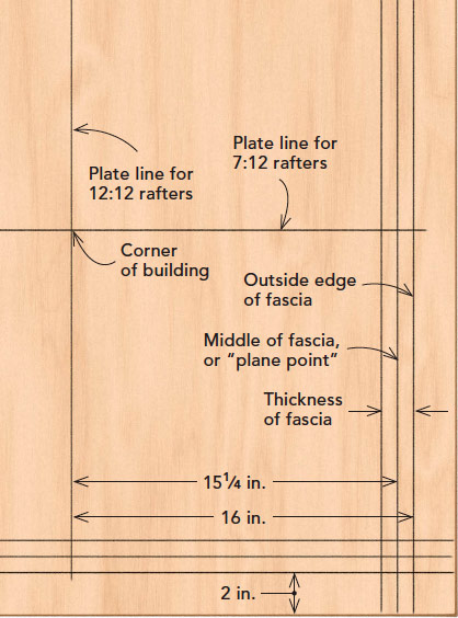 2) ESTABLISH THE OVERHANG

I start with lines representing the outside of the fascia. Beginning at the bottom right corner, draw lines 2 in. in from both edges, extending them to the edges at the top and bottom and left and right, making sure they’re square to the edges of the plywood. The blade of a framing square, which is 2 in. wide, is an easy way to get this offset.
I then mark the thickness of the fascia, and half the thickness of the fascia, and draw lines extending to the end of the sheet to represent those. The half-thickness line is what I call the “plane point”—it’s what I plane my sheathing to. You don’t have to do it this way, but it makes for a clean transition from the fascia to the roof deck for the drip edge.
With the fascia established, I draw the plate lines that represent the outside face of the building. This is the overhang. Measure back from the face of fascia the full depth of the overhang in both directions. I’m working in actual dimensions; in this case, the overhang is 16 in., so I measure in 16 in. from the outside of the fascia. The intersection of these plate lines gives you both an inside corner and an outside corner.
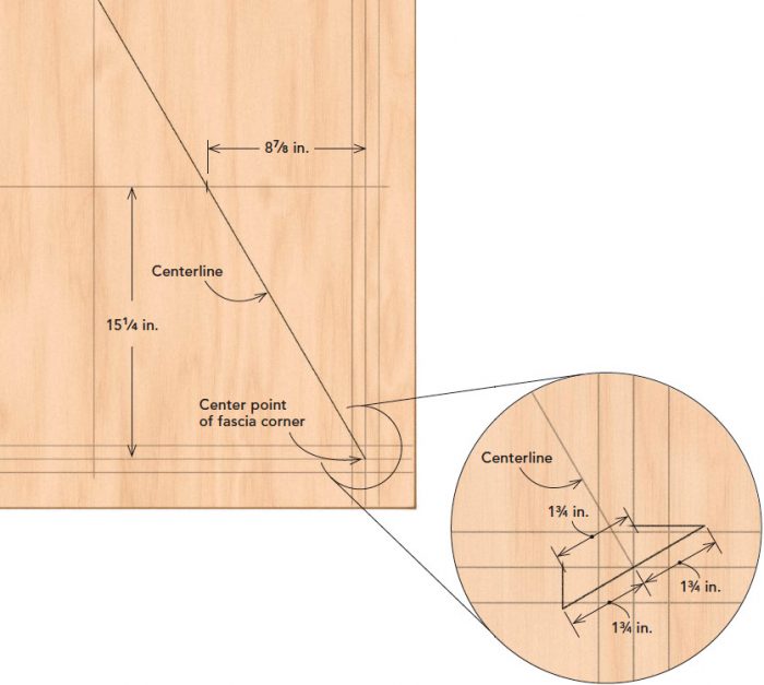 3) MARK THE CENTERLINE
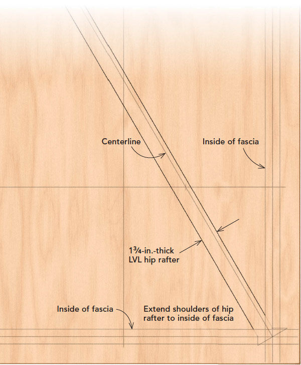
The next step is the key that opens all doors: establishing the plan-view angle of the hips and valleys. Hips always favor the steeper pitch; they’ll move back along the plate that carries the steeper slope (it’s the exact opposite with valleys). Here we’re working with a 7-in-12 and a 12-in-12, and we need to determine where the two pitches come together. Our run is 16 in. from the outside of the fascia to the plate line. The plane point where I want the sheathing to hit the fascia is 3⁄4 in. back from that, leaving 15-1⁄4 in. That’s the run. In a construction calculator, punch in 15-1⁄4-in. ‘RUN’, 7-in. ‘PITCH’, then hit ‘RISE’. The 7-in-12 side of the hip rises 8-7⁄8 in. over that run. Now we need to figure out where the 12-in-12 side of the hip rises 8-7⁄8 in. That’s easy with a 12-pitch, because it is a 45° angle from horizontal. So 8-7⁄8-in. ‘RISE’ on a 12-in. ‘PITCH’ is 8-7⁄8 in. of run. (For another pitch, say a 9-in-12, simply punch in 8-7⁄8-in. rise, 9 in. ‘PITCH’, then hit ‘RUN’, and the calculator will tell you exactly what the run is that you need). To locate the intersection of the 7-in-12 and 12-in-12 on the plate line, measure 8-7⁄8 in. from the plane point along the 7-in-12 plate line and mark it. Strike a line from the center point on the fascia corner (it’s the same plane point whether it’s an inside or an outside corner) through the mark on the plate line, and extend this line to the edge of the sheet. This becomes the shared center for both hips and valleys. This line never moves. The hips will shift around it (the valleys won’t), but that line will always be there. Mark this line as the centerline to keep track of what’s what.
 4) SHIFT THE LOCATION OF THE HIP

In order for the fascia to line up on a bastard hip and have equal overhangs, the hip has to shift over slightly. Figuring this out is easy using the French scribe technique. Draw a perpendicular line off the center corner of the fascia, measuring the thickness of the hip material in each direction. Here we’re showing a 1-3⁄4-in. LVL. Mark 1-3⁄4 in. in both directions off the end of the centerline. Then, from the ends of this perpendicular line, draw lines square to the center of the fascia (plane point). The distance between where these two lines hit the plane point is exactly the material width. Notice that these intersections are different distances from the centerline—this is called “plumb-line shift,” and it has to happen to align the roof planes. The French scribe technique gives you the actual location of the shoulders of the hip rafter.
From those points, draw the outside edges (shoulders) of the hip. To do this, measure the distance from each of the points representing the shoulder of the hip back to the shared center, or just measure the length on one side, draw the line, and then measure and mark the material width (1-3⁄4 in.) off that line. I only carry these lines to the inside of the fascia because that’s where they get their tail plumb cuts. Notice the bevel angles of those plumb cuts are right there.
 5) MARK THE BIRDSMOUTH

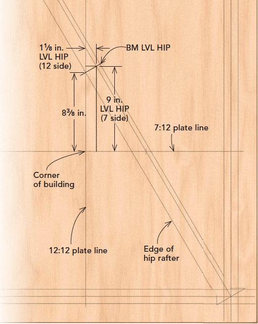
I don’t want to cut a giant bevel on my birdsmouth—I’m going to square-cut that. But you can see where the hip hits the plate line. Square across the hip from this point. I usually extend this line to make it really obvious and label it—in this case “BM LVL HIP.”
Then I mark deductions and other things that are important for layout. First, I mark the distance from the outside corner to the edge of the hip rafter—how far its edge is offset from the corner. That’s a simple measurement—here it’s 8-3⁄8 in. This is important mainly for marking the plate line when “stacking” (the roof-framer’s term for assembling) the roof. We mark this measurement on the plate to know exactly where the edge of the hip is supposed to sit in relation to the corner.
To calculate the hip rafter’s run, you need to know the run to the ridge from both plate lines; the hip’s run is just the hypotenuse of that triangle. The distances from the plate lines to the centerline at the back of the birdsmouth—the point I’m calculating the hip’s length to—become deductions or additions to the runs for each pitch. In this case, because the hip moves away from the 7-in-12 plate line, I’d subtract the distance from the corner to the center of the birdsmouth from the run on the 7-in-12 side (9 in.). The distance from the center of the birdsmouth to the 12-in-12 plate line gets added to the run on the 12-in-12 side (1-1⁄8 in.).
 6) CENTER THE VALLEY

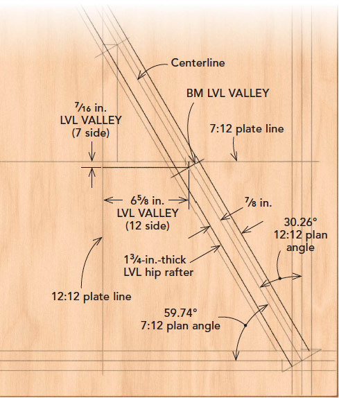
Unlike hips, valleys don’t need to shift off the centerline to maintain the proper overhang, so I center them on it. The trick here is to stop looking at the drawing as an outside corner and look at it as an inside corner. The biggest thing you’ll notice is that the valley rafter shares the plate line with the shallower pitch, while the hip shares the plate line with the steeper pitch. That’s always true.
Starting at the centerline, measure and mark half the thickness of the valley framing material in each direction—in this case, 7⁄8 in. each way. Run these lines out to the edge of the sheet, starting at the inside edge of the fascia, which creates an inside corner on the end of the rafter. The angles at this corner are exactly what I’m going to cut on the end of the valley to catch the 2x subfascia.
I also square-cut the birdsmouth for the valley. Just like I did for the hip, I draw a line from where the valley hits the plate line square across the valley rafter.
Next I determine the adjustments I need to make to the run to figure the valley rafter’s length from the ridge to the center of the birdsmouth. I mark lines from the point where the birdsmouth hits the centerline square to both plate lines. Here, that center point is 6-5⁄8 in. from the plate line on the 12-in-12 side, and 7⁄16-in. from the 7-in-12 side plate. These lengths are used when calculating the run of the valley. In an irregular situation, valleys are always longer than hips, and the drawing provides an easy way to check that your calculations are correct. Measure the distance from the valley birdsmouth to the hip birdsmouth; the valley’s run will always be longer than the hip’s run by this amount.
7) FIND THE PLAN ANGLES
I typically draw in the ridges, but they’re really only useful to include when you have a broken hip or want extra accuracy when calculating valley-jack lengths. All of the plan angles—which are also the bevel angles needed for cutting—are already on the drawing. You can use an angle finder or rafter square to measure them. If you want a bit more accuracy, you can use math. One method is to simply plug the rise and run of one of the triangles on the drawing into a construction calculator and hit the ‘PITCH’ button, and it will tell you the angle (in our example, 7-in. ‘RISE’, 12-in. ‘RUN’, ‘PITCH’ = 30.26°). Because we’re working off of square corners, all we need to do to get the opposite bevel is subtract that angle from 90° (90° – 30.26° = 59.74°).
The plan/bevel angles on any irregular roof that includes a 12-in-12 pitch are the easiest to figure; the plan/bevel angle of the 12-in-12 side is simply the slope of the opposite pitch. All you need to do to find that is look it up on a framing or rafter square or get it right out of the calculator (for the 7-in-12 pitch here, simply punch in 7-in. ‘PITCH’, ‘PITCH’ to get 30.26°).
8) DEVELOP RUN, PITCH, AND BACKING ANGLES
For every 12 in. a common rafter runs, a regular hip or valley travels 16.97 in. This length (nearly 17 in.) is what framers call the “unit run” of a natural hip or valley. This is not the unit run, though, for irregular hips and valleys. You have to figure that out for whatever combination of pitches you’re working with. You can do this using a framing square right on the drawing, but for better accuracy, I calculate it. That’s easy when one side is a 12-in-12 pitch; you simply punch in one pitch as rise, the other as run, and hit diagonal (7-in. ‘RISE’, 12-in. ‘RUN’, ‘DIAG’ =13-7⁄8 in.). When neither pitch is a 12-in-12, (say one is a 5-in-12 and one a 9-in-12) there are a couple steps. First, punch in the shallower pitch as rise, the steeper as run, and hit (5-in. ‘RISE’ , 9-in.‘RUN’ , ‘PITCH’= 6-11⁄16 in.). Then punch in that calculated pitch as ‘PITCH’, enter 12-in. ‘RUN’ , and hit ‘DIAG’ to get the unit run (in that case, 13-3⁄4 in.).
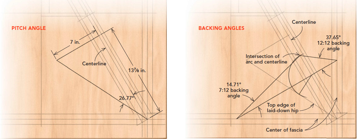
For the example in this article, 13-7⁄8 in. is our unit run. That means our hip or valley rises 7 in. for every 13-7⁄8 in. of run along its length. This rise and run is also the pitch of our hip or valley rafter, and we need to know what that is in degrees. Again, we could simply measure it with an angle finder if we drew it out (which we will in a moment). I use the calculator. Punch in 13-7⁄8-in. ‘RUN’, 7-in. RISE’, ‘PITCH’= 26.77°.
The unit-run measurement comes into play for rafter calculations, but also for figuring out the backing angles for the hips and valleys. I back-cut all of my hips and valleys so the sheathing has more of a surface to rest on, and it makes stacking easier and more accurate. (I’ve had this argument with lots of other carpenters who don’t back-cut their hips and valleys. They argue it’s not necessary—and it’s not. But then you need to adjust the birdsmouth cut to bring the hip or irregular valley into plane with the other rafters. By back-cutting, you don’t; The jack rafters will plane with them perfectly. But really, back-cutting is more important with the valleys. When you have a valley plowed out, you don’t have to use a pencil or square to plane the top of the jack with the centerline of the valley. You just hold the top edge of the cheek cut on the jack flush with the shoulder on the valley, so you know it’s an absolute perfect plane.)
With irregular pitches, the angles on the shoulders of the hips and valleys are uneven. It’s easy to figure out these angles. Starting at the intersection of the centerline and plane point, measure up the unit run—in this case, 13-7⁄8 in. Then measure the shallower pitch perpendicular off of that—7 in. in this case. Connect the end of that 7-in. line back to the center of the fascia (plane point). The triangle this forms represents the hip or valley rafter laid on its side (you can measure the slope right from this with a protractor or angle finder).
To develop the backing angles, draw a line perpendicular to the “top edge” of this laid-down hip, starting anywhere along this top edge and back to the centerline (you’re going to develop the same triangle no matter where you start). Using that intersection as the center, set a compass to the length of the line you just drew, and swing an arc from where the line started back to the centerline. (You don’t need to actually swing an arc; you just need to mark the centerline up the same distance as the line from the centerline to the top of the laid-down hip.) Draw a line perpendicular to the centerline, running through the center point of the arc you just drew, going all the way to the plane point on both sides of the centerline. Connect the points where that line intersects the plane points back to where the top of the arc hits the centerline. What you get is a triangle that represents the backing angles for the hips and valleys. Again, you can measure these with a bevel gauge or protractor, or measure the rise and run of the triangles and use a calculator to get the angles. For these, the angles are 37.65° for the 12-in-12 side and 14.71° for the 7-in-12 side. Now, if you take any circular saw and try to set the bevel at 14.71°, it’s about impossible. If you bevel these at 15° and 38°, you’ll never see that difference. Label these angles on the drawing. If you want to go further, you can step off your on-center spacing from the plane point along the fascia in both directions and measure back to the hip to get the run for the common difference for jack rafters.
And with that, you have every piece of information you need to calculate every single piece of wood on the entire roof on a piece of plywood. Once everything’s penciled in, I go over it with different colors of fine sharpie to make everything easier to distinguish when figuring and so it holds up better under job-site conditions; pencil does tend to fade in the sun.
RELATED LINKS
- Aligning Eaves on Irregularly Pitched Roofs
- Roof Framing Revisited
- Model and Measure Part One: Hip Rafters Demystified by Visualizing in SketchUp
Fine Homebuilding Recommended Products
Fine Homebuilding receives a commission for items purchased through links on this site, including Amazon Associates and other affiliate advertising programs.
Flashing Boot
Stabila Extendable Plate to Plate Level
Portable Wall Jack



View Comments
On using additional height by staking several plates shown in this article.
I'm wondering why longer studs aren't used instead of so many top plates for the additional height? Each plate adding more thermal bridging layers in colder climates? I have seen how in Sweden (lots of snow there!) they use a different building method. On a 2X6 or greater stud wall, they cut out a 'vertical' 2X6 piece from the 'top exterior side' of each wall stud. Then a single top plate covers, caps, the studs and the vertical 2X6s. This produces 7 inches of support to all walls and only one (1) thermal bridge. It also saves a lot of wood. Any engineers out there, can you comment please? I took the picture off my laptop screen. A video, One of the builder's houses had burned down before he moved in and was starting over. I'm in that same 'boat' https://www.youtube.com/watch?v=4nRz0D0bNmg