
Installing Low-Voltage Fixtures
12-volt systems are safer to work on, but you still need to turn off the power.
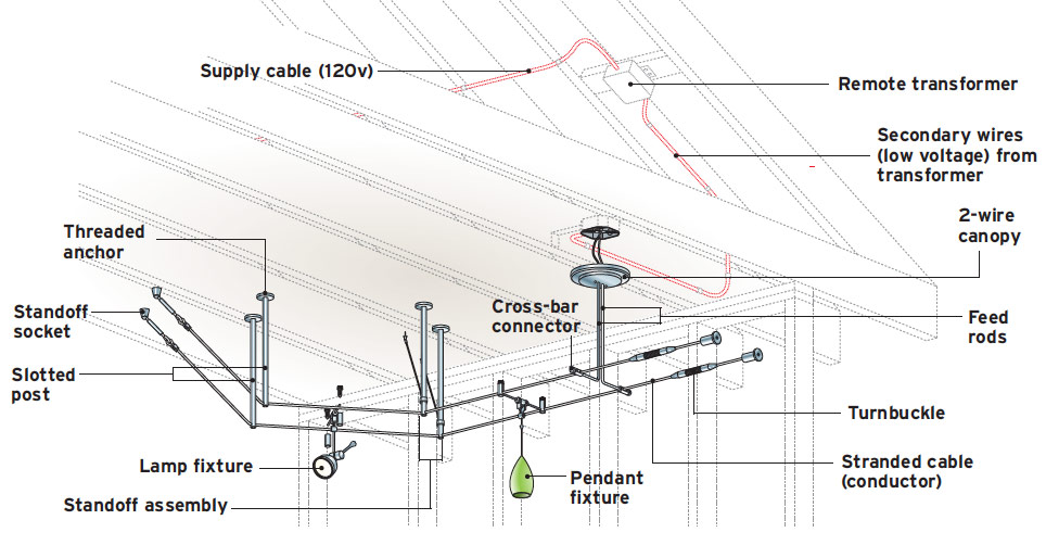
Low-voltage lighting systems are installed inside and outside houses and typically operate on 12v current, so they require a transformer to reduce standard house voltage from 120v. Transformers vary—some are coil-wound magnets, whereas others are electronic—so follow the installation instructions provided with your unit.
Lo-vo systems have become extremely popular because, with voltage roughly the same as a car battery, there is little risk of shock or electrocution. However, the large currents used in some instances can create a fire hazard if connections are poor. Systems can also be creatively constructed from a variety of different lighting materials. Lo-vo systems can generally be controlled by standard switches or dimmers, but you should check the literature that comes with your system.
Though it’s safe to touch the tracks of a lo-vo system, you should turn off the power when working on the system. The upstream part of the system (between the transformer and the power source) has 120v power, which could deliver a fatal shock. On the low-voltage side, there is a potential to short the system and damage the transformer.
After installing all the parts and doing a preliminary check of the system, it’s safe to energize the system. (Note: Because any high-intensity bulb can get very hot, do not install any cable fixtures within 4 in. of a combustible surface.) Track-lighting systems are inherently complex, so read the instructions carefully before you begin the installation.
Safety and low-voltage systemsIf you install your lo-voltage system correctly, and are careful never to touch the supply wires that run to the transformer, you can touch energized lo-vo tracks without getting shocked—but that doesn’t mean you should. Always shut the power off before doing any work on an electrical circuit. Best to be too cautious . . . and stay safe. |
|
Anchoring Low-Voltage Standoffs
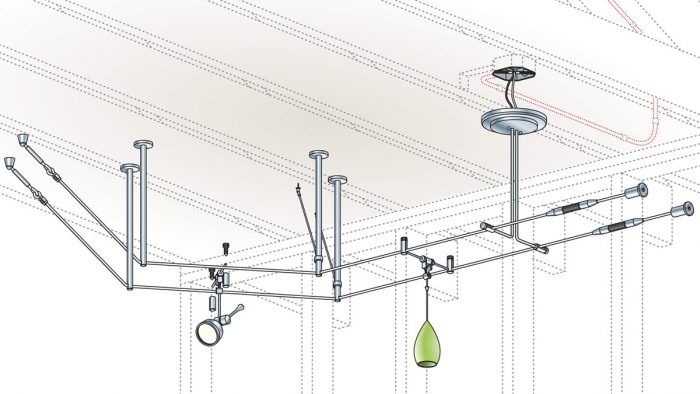
The key to a good-looking, correctly functioning cable system is getting the cables taut and level. Thus your first task in installing a lo-vo system is finding solid locations in which to anchor the cables. In this installation, the principal anchors were standoffs in each corner so the cable could be stretched around the perimeter of the room. Alternatively, you can anchor standoffs in a ceiling to support cables and bulbs. Standoffs are also called re-routers because cables often change direction as they emerge.
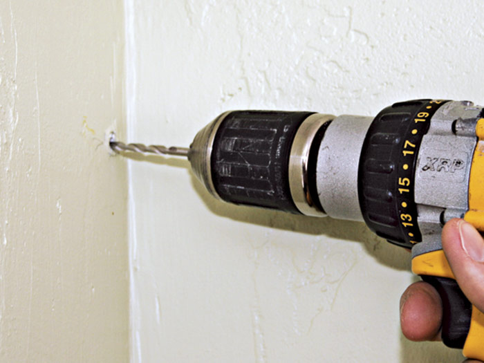
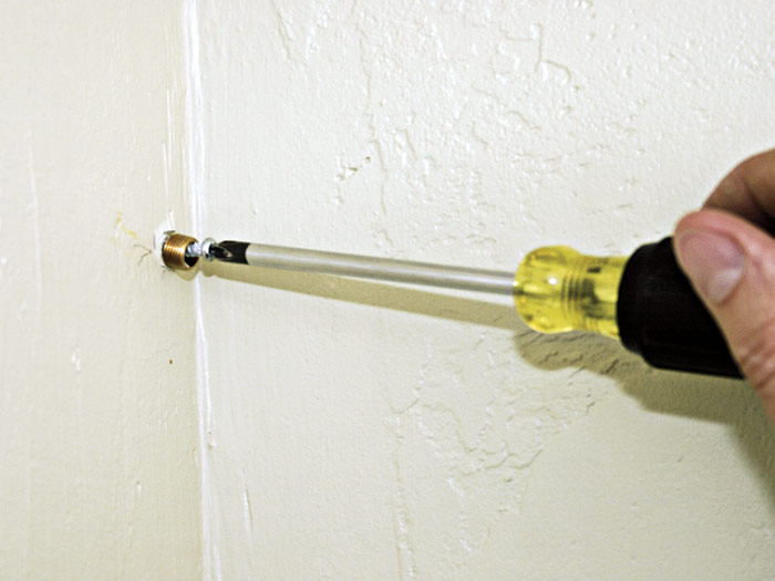
Use a laser level to establish level anchoring points around the room. Predrill holes in the plaster for anchor screws 1. Plaster is harder than drywall and there may be lath nails in the way, so wear goggles and have extra drill bits on hand.
 |
 |
 |
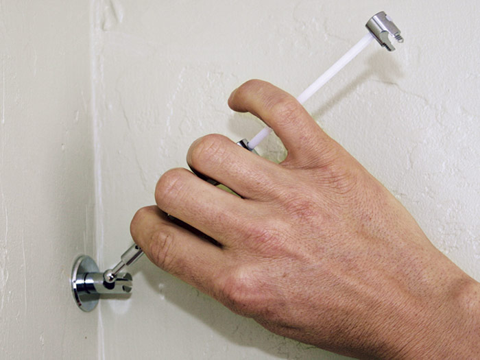 |
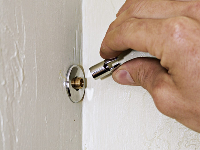
Because cables will be stretched taut, standoff anchors must be screwed to wood framing—in this case, into doubled studs in the corner 2. Use screws at least 2 in. long to attach the anchors. After sliding a chrome base plate (washer) over the anchor, screw the standoff socket to the exterior threading of the anchor 3. Insert the ball end of the fiberglass rod into the standoff socket 4. This ball-and-socket assembly allows the standoff to swivel freely so you can fine-tune the cable positions. The cables will be spaced 4 1⁄2 in. apart.
Running Cable
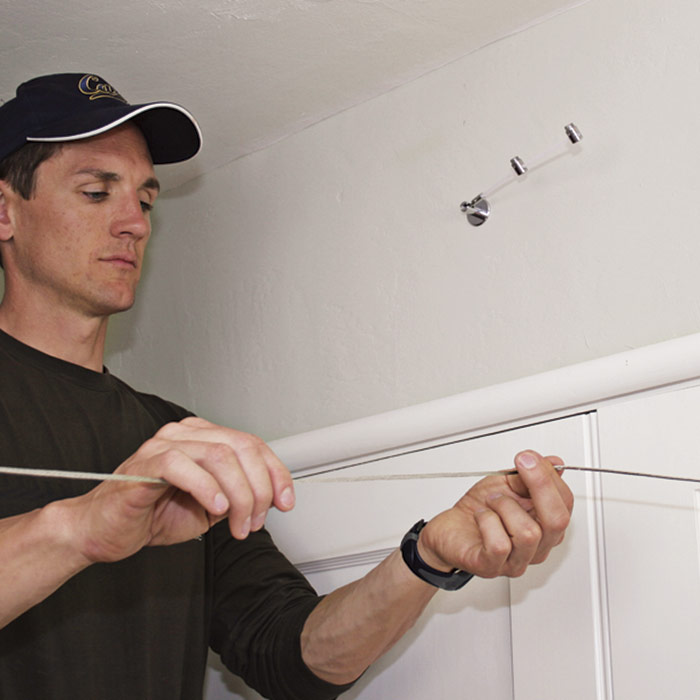
The next step in installing this system is to run the cable. Note the standoff at the top of photo 1. Because the walls in this room were only 12 ft. apart, both cables could be run through a single angled standoff with two slotted posts, located in each corner. If the walls are farther apart, you may need a cable support in the middle of the run.
Measure the cable length you need and cut it 3 in. to 4 in. longer than your measurement so you can insert the ends into turnbuckles without having to struggle. Once you tighten the turnbuckles and tension the cable you can snip off any excess cable. On the other hand, if you cut a cable too short, you’ll have to discard it and start again with a new piece.
Place each cable into a slotted post, rather than pulling it through the slot, whose sharp edges can cut into stranded cable 2. (This is a quirk of the particular system shown here; other standoff types allow you to pull cable more freely.)
| PRO TIP: When working with stranded cable, tape the cable ends and then cut in the middle of the tape to keep the strands from unraveling. |
After placing the cable into a slotted post, screw on the post cap to keep it from popping out when the cable is tensioned 3. As you place the cable into the subsequent standoffs, loosely tension it to take up the slack 4. With this system, the second cable will be about 4 1⁄2 in. from the first.
 |
 |
 |
 |
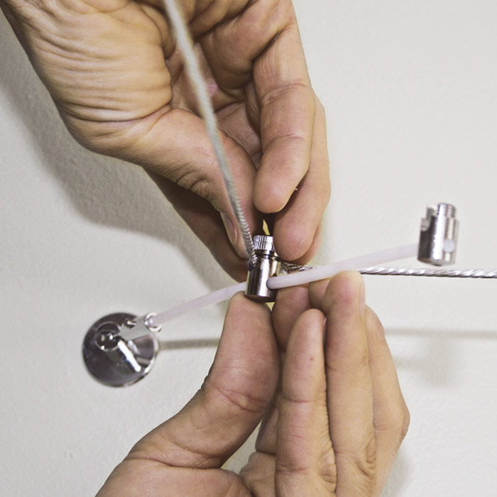
Tensioning Cables
Correctly installed, the cables of a low-voltage system should be more or less horizontal and equally spaced (parallel along their length). As with most systems, this installation uses turnbuckles to tighten the cables after they have been placed in the standoffs. The cables’ Kevlar® core prevents stretching or sagging once the lightweight fixtures have been installed.
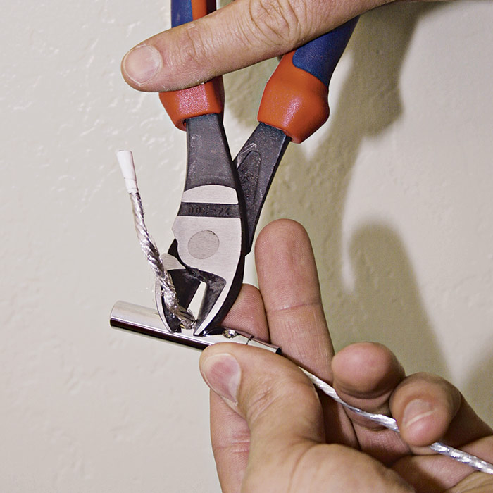
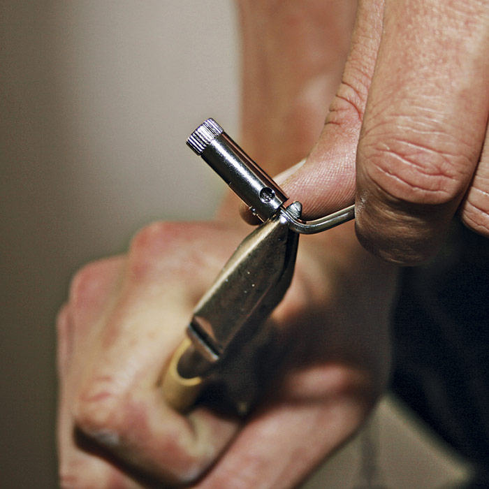
Once you’ve loosely run the cable, insert an end into a turnbuckle 1. The cable end feeds in the end of the turnbuckle and exits in a slot in the middle. Tighten the setscrew(s) on the assembled turnbuckle to keep the cable from pulling out, then trim the excess cable sticking out 2. Don’t rush trimming the cable: Wait until you’ve made final adjustments to the whole layout before trimming.
 |
 |
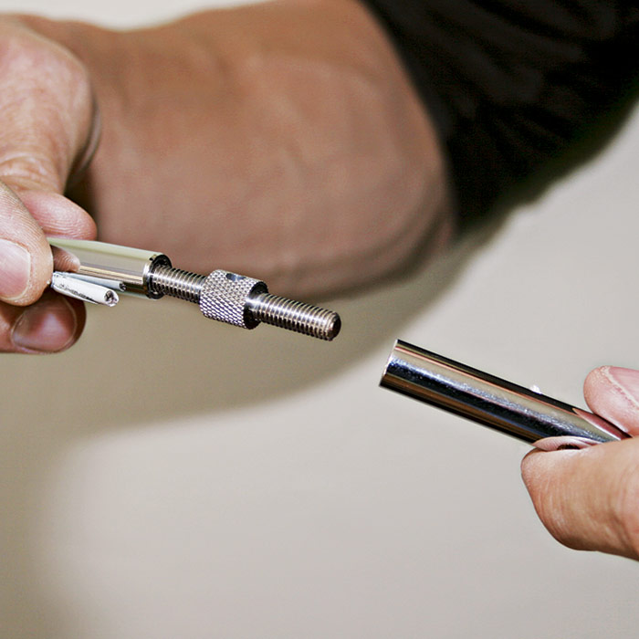 |
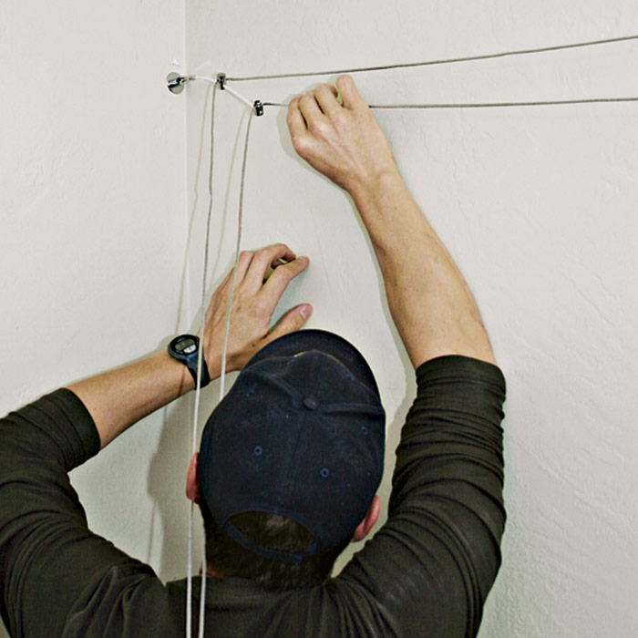
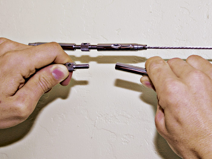
A turnbuckle’s center post has a thumbscrew with threads on both ends. As you turn the thumbscrew in one direction, it draws tight both ends of a cable; turn in the opposite direction to slacken cable tension 3. With cable attached to both sides of a turnbuckle, the installer may struggle to draw the cable tight enough to join them 4. This is a good reason not to trim the cable until the turnbuckle starts tightening both ends.
 |
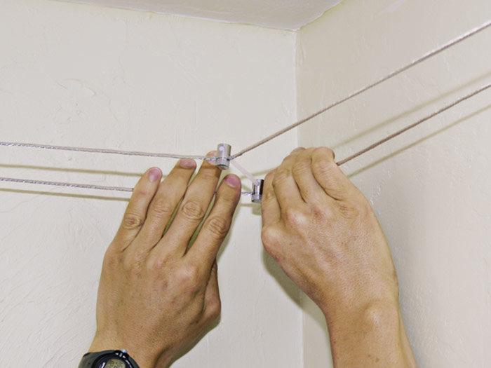 |
A certain amount of adjustment is necessary after both cables are taut. Here, the installer adjusts the cables so that the standoff comes out of the corner at a 45-degree angle, thus ensuring that the wires will be equidistant 5.
Locating the Canopy
Once the tensioned cable has been installed, you’ll need to locate the canopy. The canopy (also called a canopy feed) receives low-voltage current from the transformer and delivers it to the cables. The canopy mounts to a junction box on the ceiling or wall.
| PRO TIP: Fixture canopies are often polished chrome, which is easy to cloud with fingerprints. Wearing lightweight plastic gloves solves the problem; nitrile plastic gloves are especially flexible. |
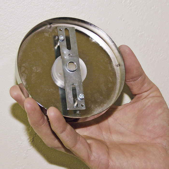
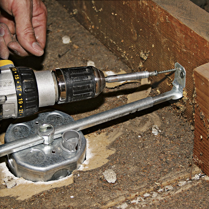
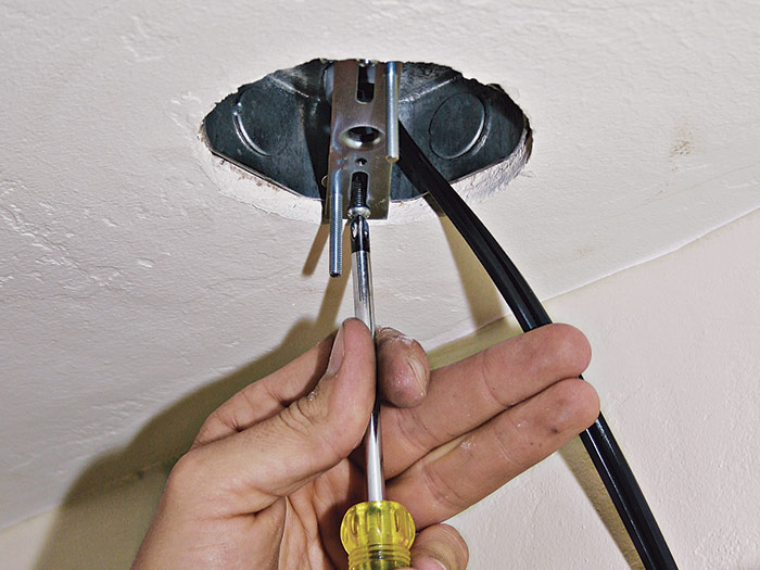
Before installing the canopy, make its holes—or those of its mounting bracket—line up to the holes of the junction box you’ll be installing in the wall or ceiling 1. The slotted mounting bar on the back of this 2-wire canopy can fit several box widths.
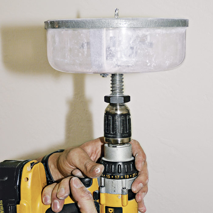
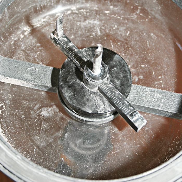
If the canopy will be ceiling mounted, drill a hole for it. To minimize the mess, use a hole-cutting tool with a dust cover 2. Note: A screw gun with a 1⁄2-in. chuck will accept large-shank tools such as the one shown here. Set the hole-cutting tool’s blade to the diameter of the junction box 3. For large holes, this tool has a counter-weight that attaches to the right side of the cutting bar to balance the torque of the blade.
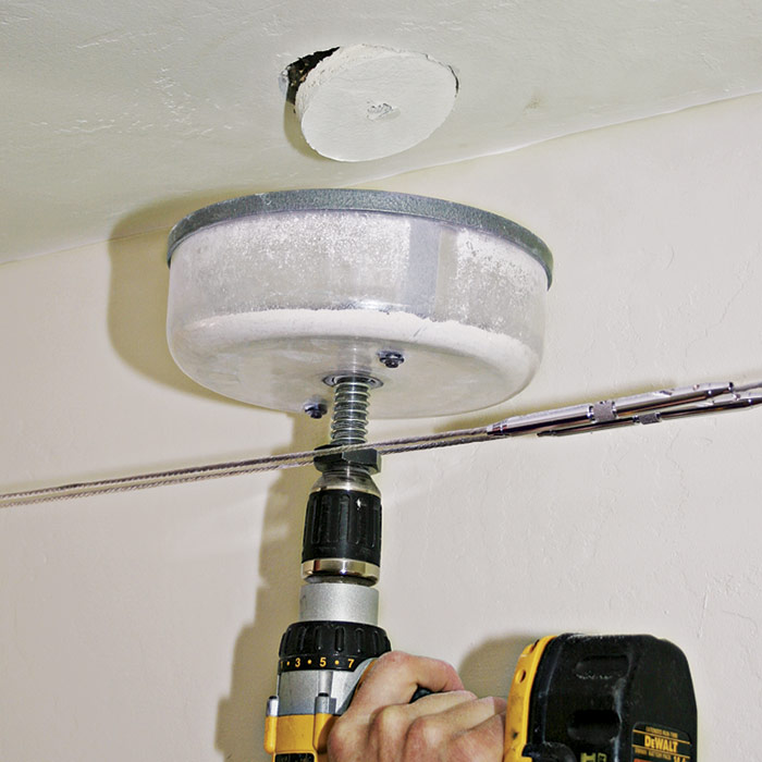
Hold the cover of the tool snug against the ceiling so it can contain the dust 4. Wait a few seconds for the dust to settle inside the cover before lowering the tool.
 |
 |
 |
 |
Mounting the Box & Wiring the Transformer
After the canopy has been located, it’s time to mount the box and wire the transformer. The transformer shown here permits 12v or 24v wiring. Your installation may vary, so follow the instructions provided. Note: All wiring is done with the power off.
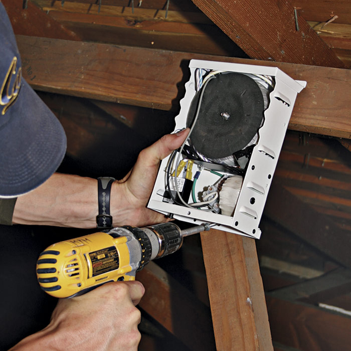
When retrofitting a ceiling box, bend up the bar tabs to make them easier to nail or
screw. Extend the support bar until its tabs are snug against joists, adjust the height of the bar so the box is flush to the ceiling, and then screw the tabs to joists 1.
 |
 |
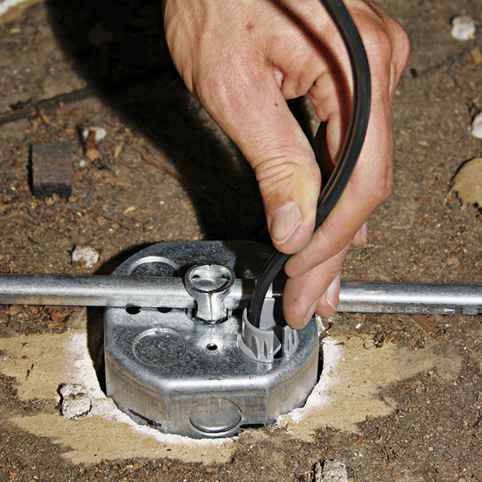 |
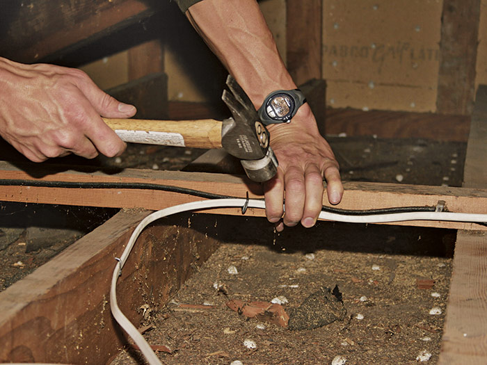
Install the transformer above the insulation so that its vents work properly and the unit can be accessed easily 2. Run the secondary (lo-vo) cable between the transformer and the ceiling box, stapling it within 12 in. of a box and every 4 ft. along its run 3. Feed the other end of the lo-vo cable into the transformer 4. The gray cable connectors are one-way clamps: easy to insert but difficult to pull out.
Run the supply cable (120v) from an existing switch to the transformer 5. Protect the cable by stapling it to the side of a joist or to a runner added for the purpose.
 |
 |
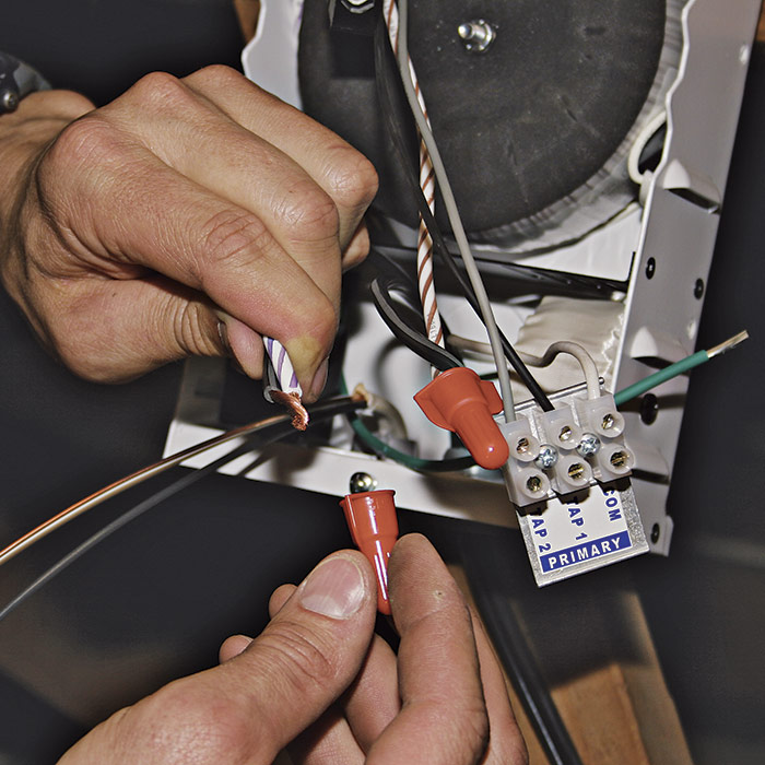
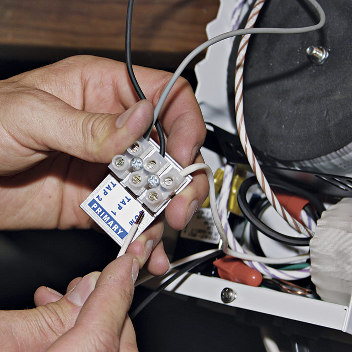
After stripping 1⁄2 in. of insulation off the wire ends, use wire connectors to splice the secondary wires, which run from the transformer to the ceiling box 6. Next, splice the primary ground wires, using a wire connector. Then connect the primary neutral to the common (neutral) terminal, as shown, and the primary hot wire to one of the tap terminals. Tighten the terminal screws to grip the wires 7.
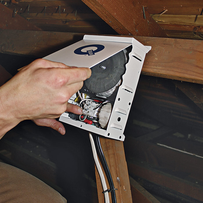
Close the transformer cover to protect the connections inside 8.
 |
 |
 |
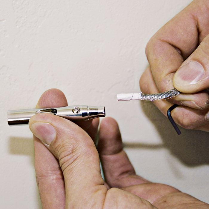
Installing the Canopy
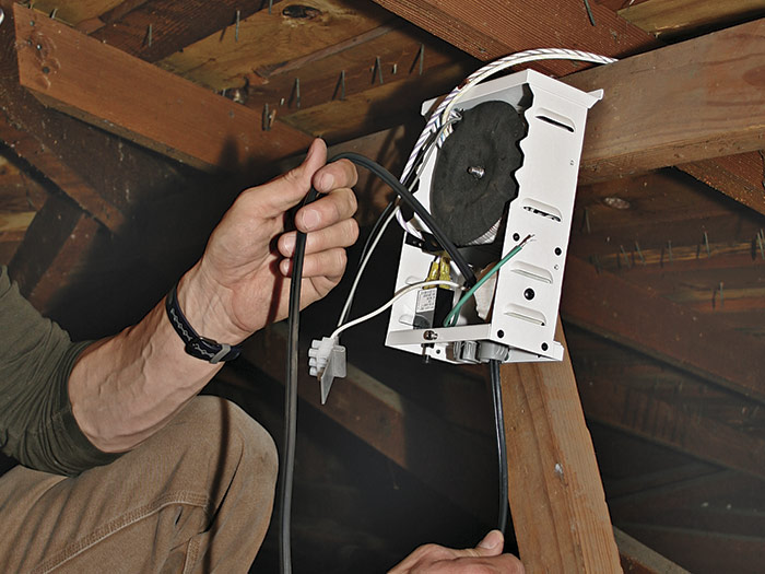
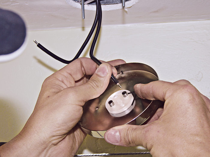
The canopy is installed after the transformer has been wired. Install the mounting bracket to the new ceiling box; it will support the canopy that supplies lo-vo power to the cables 1. The wire hanging from the box is the secondary (lo-vo) cable from the transformer.
Separate and strip the two wires in the lo-vo cable and solder their ends. Soldering fine-strand wire makes it solid and unlikely to smash flat as you tighten down the set screws on the canopy terminals. Soldered wire is also less likely to arc and overheat 2. (Note the tiny Allen wrench inserted into the setscrew on the right of the photo.)
 |
 |
 |
 |
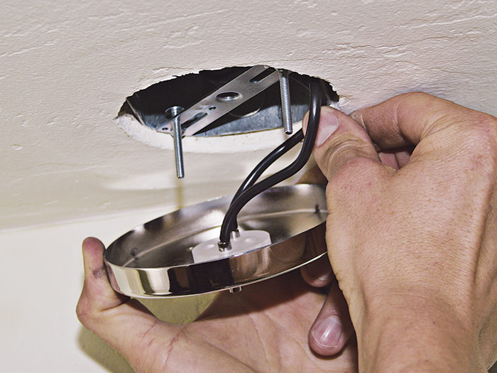
Use mounting screws that are long enough to extend beyond the canopy face 3; they’re faster to install than short screws because they give you room to maneuver.
Slide the canopy over the mounting screws and turn the canopy cap nuts onto the mounting screws 4. When the nuts bottom out on the screws, continue turning the cap nuts, which will turn the extra-long screws back up into the box. This will make the canopy nice and snug.
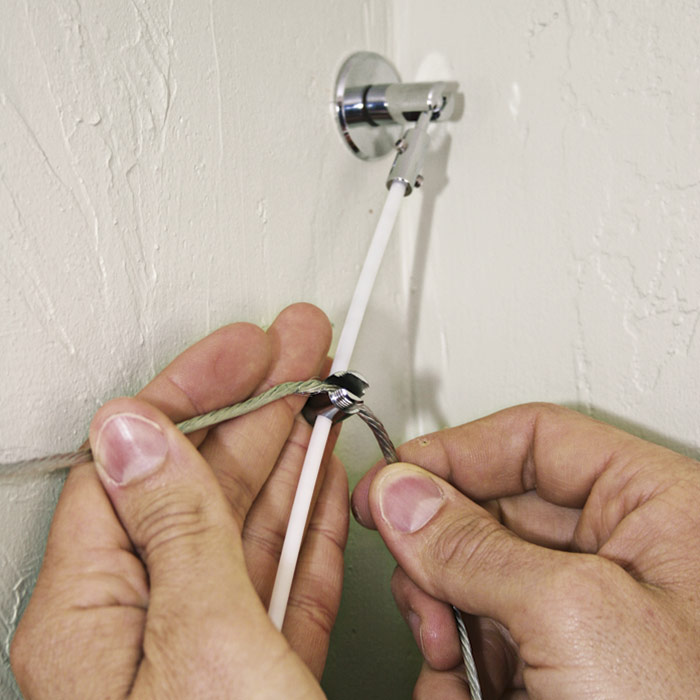
Attaching the Feed Rods & Fixtures
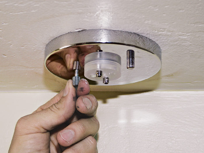
The final task for installing a low-voltage system is adding the feed rods and fixtures. The feed rods transfer low-voltage current from the canopy terminals to the cables. Setscrews on the terminals secure the rods.
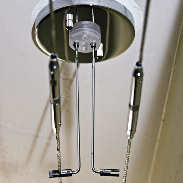
Because the canopy is centered over the two cables, you may need to bend the feed rods to bring them to the cables 1. Secure the rods in a vise between two wood scraps (to minimize marring the finish) and bend them at the point equal to the distance from the canopy to the cables. Some systems will provide horizontal connectors for this purpose, eliminating the need for bending.
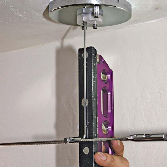
Bend the first rod and test-fit it, using a torpedo level to ensure that the rod is plumb and the cable is still level 2. If the first rod fits well, use it as a template for the second. Repeat the process with the second feed rod. Note that rod ends are slotted like the standoff posts that anchor the cables in the corners of the room. A cap nut screws on to the slotted rod end to capture the cable 3.
 |
 |
 |
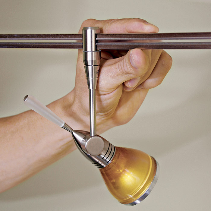
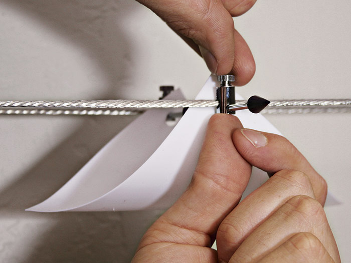
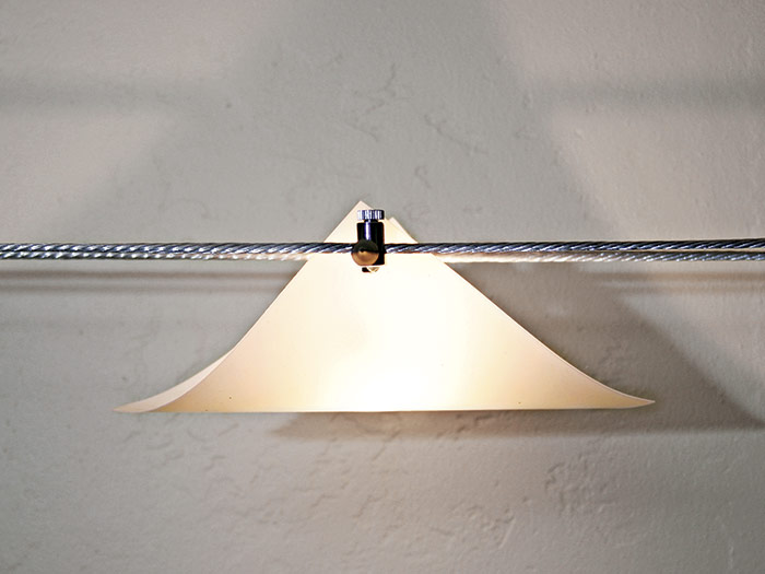
Insert the bulbs into the fixtures before you attach fixtures to the cables. If your system uses halogen bulbs, don’t touch them with your bare hands because the oil in your skin will shorten the bulb life. In general, fixtures need to connect to both cables to become energized, so each fixture has a crossbar that spans the cables. Hand-tighten the fixture connectors so they’re snug 4. After you’ve installed all the fixtures and surveyed the system, turn on the power 5.
 |
 |
Excerpted from Wiring Complete, 3rd Edition (The Taunton Press, 2017) by Michael Litchfield and Michael McAlister
Available in the Taunton Store and at Amazon.com.
