Replacing a Single-Pole Switch
Be prepared for anything in remodel wiring, but be sure to test, disconnect, and attend to any code violations, before reconnecting the wires to the new switch.
The old saw in remodeling, “You never know what you’ll find till you open the wall,” is especially true to remodeled wiring. Be prepared for anything, form a plan based on what’s there, and follow the code and common sense as you proceed.
Testing is the essential first in wiring
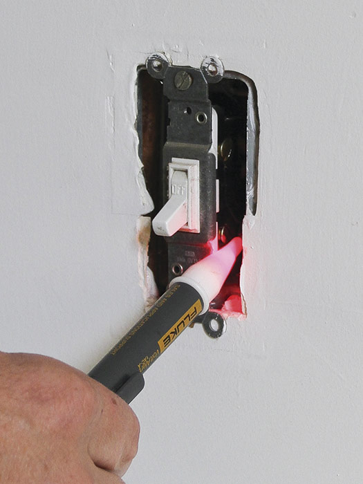
First test the tester. If the switch is working, turn the light on and have a helper at the service panel flip breakers till you find the one controlling the switch’s circuit. Turn that breaker off and lock the panel; if it’s a fuse box, remove the fuse. If the switch isn’t working, remove the cover plate and touch the tester to both wires attached to the switch 1. Flip the switch toggle to off and on positions. Have your helper at the panel turn off power to the circuit, as above. Continue testing, however.
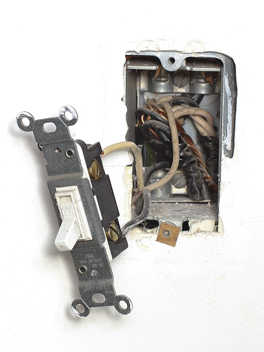
Being careful not to touch the sides of the switch, unscrew its mounting screws and gently pull it out from the box. Then test again, touching the tester to every wire—white, black, and ground—and to spliced wire groups inside the box. If your noncontact tester indicates no voltage, it’s safe to handle the wires.
 |
 |
Disconnect switch wires and note their condition
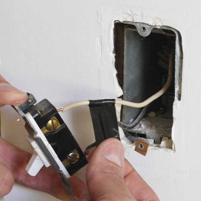
If the wire insulation is intact (not brittle, cracked, or falling off), the wires are probably safe to attach to the replacement switch. But first scrutinize the inside of the box. In the sequence shown, we found several things that needed attention 2 before we could wire a replacement switch: (a) the metal box was ungrounded, (b) though wire groups were twisted together and taped with electrical tape, they lacked a solid mechanical connector, (c) the white wire attached to the switch, though being used as a hot lead to the fixture, was not identified as a hot wire, and (d) the box was full of dust and debris.
Attend to any code violations
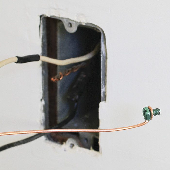
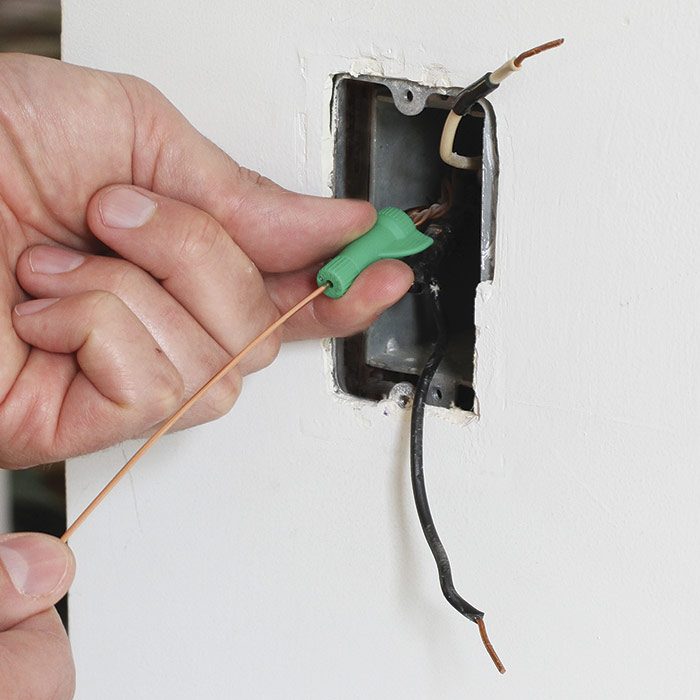
We started by vacuuming the box, which also gave us a better view of its contents. After unwinding tape from each wire group, we looped a bare ground lead wire around a ground screw 3, screwed it into a threaded hole in the back of the box, and spliced that new lead wire to the ground-wire group, using a special grounding connector 4. This grounded the metal box. We next secured wire connectors to the other wire groups, using lineman’s pliers. Then we taped the white wire 5 that had been attached to the switch to identify that it was a hot wire.
 |
 |
 |
Connect the wires to the new switch
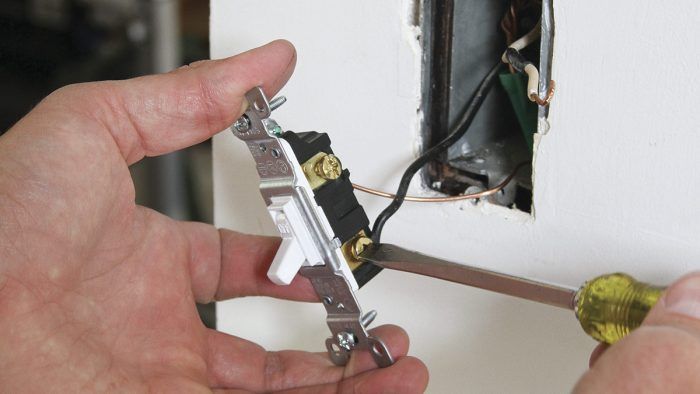
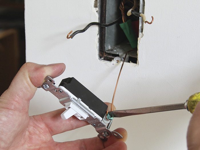
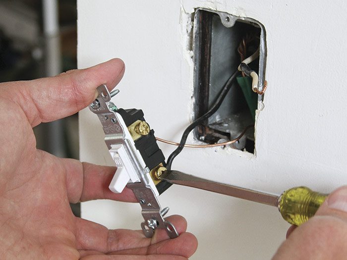
First attach the ground wire to the green ground screw on the switch 6‚. If there’s no ground wire feeding the box, code doesn’t require grounding a switch. Connect the switch-leg wire (black) 7, then the hot lead (white wire taped black), which runs to the fixture. Once the wires are connected to the replacement switch, fold them into the box, tighten the mounting screws that hold the switch to the box, and replace the cover plate.
 |
 |
Excerpted from Wiring Complete, 3rd Edition (The Taunton Press, 2017) by Michael Litchfield and Michael McAlister
Available in the Taunton Store and at Amazon.com.
