Wiring a GFCI or AFCI Receptacle
Follow these guidelines to install circuit-interrupter receptacles to protect either a single outlet or outlets downstream from risks of electric shock or fire.
Ground-fault circuit interrupters (GFCIs) and arc-fault circuit interrupters (AFCIs) offer different but critical code-required protections. In brief, GFCIs protect you against electrical shocks, and AFCIs protect against arc faults and reduce house fires. You can achieve GFCI or AFCI protection on a circuit by installing a GFCI or AFCI breaker or, as described below, by installing a GFCI or AFCI receptacle at the beginning of a circuit to protect receptacles downstream.
Note that GFCI and AFCI receptacles look similar, and wiring either type is essentially the same. So before you start your installation, check the label on the device to be sure you are installing the correct one. (For circuits that require both GFCI and AFCI protection, you can buy dual-function circuit breakers.)
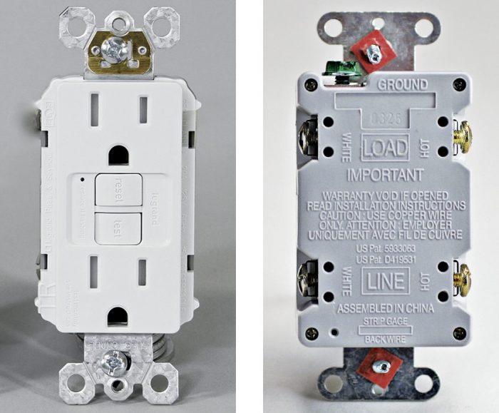
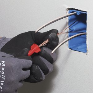
When wiring a GFCI or AFCI receptacle, it’s important to connect incoming wires (from the power source) to the terminals marked “line” on the back of the receptacle. Attach outgoing wires (to outlets downstream) to terminals marked “load.” To distinguish line and load wires during rough-in, write each term on small pieces of the cable sheathing and slip them over the appropriate wires before folding them into the box.
Protecting a single outlet
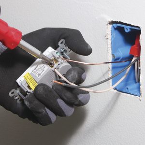
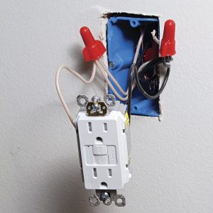
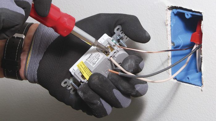
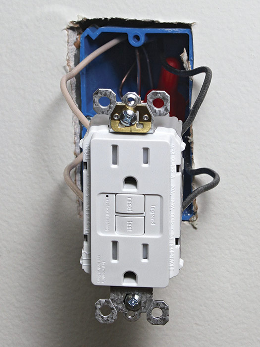
If the GFCI or AFCI is going to protect users at a single outlet 1, attach wires to only one set of screw terminals. The yellow tape across one set of screws indicates that they are load terminals. If you are hooking up the device to protect only a single point of use, leave the tape in place and connect wires only to the screw terminals marked “line.” After attaching the ground pigtail, screw down the silver screw to secure the neutral pigtail 2.
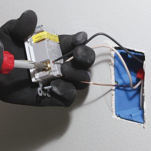
Connect the hot pigtail to the brass screw last 3 then push the device into the box carefully, hand-screw it to the box, and install a cover plate. Note: If you inserted wire ends into holes on the back of the receptacle, you must still tighten down the screw terminals on the sides of the device, which tightens internal clamps that hold the wires snug.
Feeding the circuit through a GFCI or AFCI receptacle
If you want to use a single GFCI or AFCI receptacle to protect downstream outlets, feed them from the “load” terminals of the receptacle. That is, connect incoming and outgoing cable wires directly to the device, rather than using pigtails. (You should, however, splice ground wires to ensure continuity: Screw the ground pigtail to the receptacle’s ground screw.) Again, it’s important to connect incoming wires (from the power source) to the terminals marked “line” and outgoing wires to terminals marked “load.” This is a code-approved way to offer protection downstream without using a breaker.
Attach the ground wire to the ground screw, neutral wires to silver screws, and hot wires to brass screws. If you instead inserted wire-ends into holes on the back of the receptacle, screw down all screws on the sides of the device, which tightens internal clamps holding the wires. Be patient as you push the receptacle into the box, folding wires as needed. Install the mounting screws and attach the cover plate.
Excerpted from Wiring Complete, 3rd Edition (The Taunton Press, 2017) by Michael Litchfield and Michael McAlister
Available in the Taunton Store and at Amazon.com.

