Wiring a Linear Slide Dimmer
Follow these general guidelines...but always read specific installation directions carefully before you start, as dimmer specs vary.
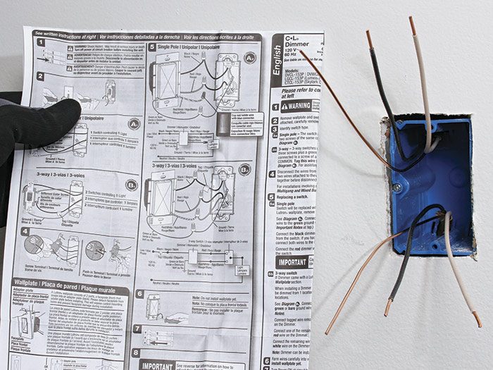
If you are replacing an existing dimmer, note: Dimmers that do not require neutral wires may be “trickle devices” that allow a minuscule amount of current flow all the time to power the dimmer. Trickle current can be enough to shock you if you work on a fixture without first turning off the breaker (or fuse) that controls the circuit. Always use a voltage tester to test the dimmer and the fixture to make sure no current is present.
All work should be done with the power off.
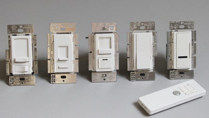
Slide dimmers have a slide bar that allows you to set the light level and a separate on-off switch so you can turn the light on and off without changing a preset light level. Slide dimmers have largely replaced the old rotary type that combined both functions. Newer slide dimmers offer additional functions, so their wiring has become more complicated, and many sport wire leads rather than screw terminal connections.
Match the dimmer to the loadA dimmer must match the type of fixture it controls, whether incandescent, halogen, fluorescent, or LED. Typically, the dimmer rating is stamped on its face. |
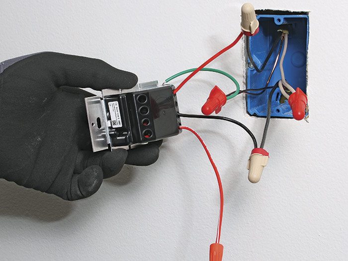
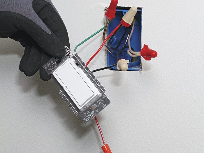
For standard single-pole switches, it doesn’t matter which screw terminals you connect a switch leg or hot wire to, but it may matter which wire you attach to dimmer leads, so always read the manufacturer’s directions. The slide dimmer shown in the photos is a multi-way switch that is convertible: It can be wired as a single-pole or three-way switch, depending on which wires you connect 1. It has a green insulated ground, red and black hot wires, and a red-and-white-striped wire that would be used as a signal wire to a companion dimmer.
Because the convertible device would be used as a single-pole dimmer, we didn’t need the red-and-white-striped wire. So we capped it with a wire connector 2. Because this dimmer does not require a neutral, we spliced the neutrals together to feed through to the fixture (without connecting them to the dimmer).
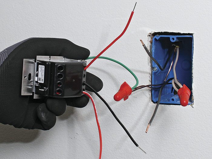
Splice the ground pigtail to the device’s ground lead. Then splice the switch leg from the box to the red lead on the device. On devices with wire leads, typically a red lead attaches to the switch leg.
Finally, attach the incoming hot wire to the other hot lead (black) on the device 3. Carefully fold the wires into the box 4 and push the wired dimmer into the box. Screw the device to the box and install the cover plate.
Excerpted from Wiring Complete, 3rd Edition (The Taunton Press, 2017) by Michael Litchfield and Michael McAlister
Available in the Taunton Store and at Amazon.com.

