Mechanical Systems in a High-Performance House
In this video, take a look at the inner workings of the FHB House project and the systems needed to heat, cool, and ventilate this airtight home.
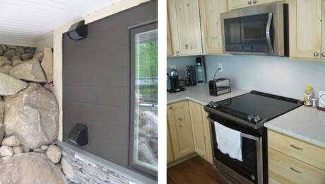
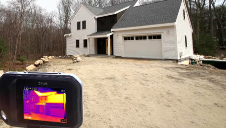
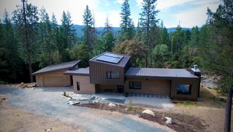
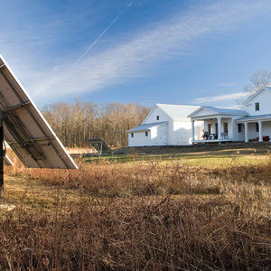
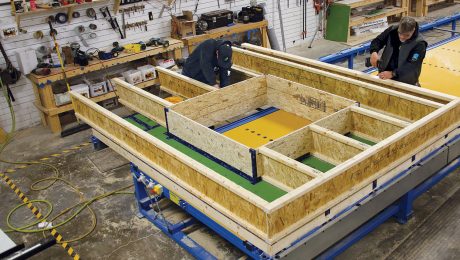
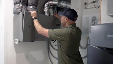
Builders are installing the mechanical systems needed for the FHB House. The roof is designed to face south for optimal use of a future photovoltaic system. A series of minisplits will take care of heating and cooling. An energy-efficient heat-pump hot water heater serves the house’s needs. There is optimized ductwork in place for a conventional clothes drier. The garage also features its own ventilation system. Watch this video to learn more.











View Comments
If a future homeowner switched to a conventional dryer, would there be a need to bring in make up air?
Nice video. Could you provide some detail on how you trimmed out the celling unit for the mini split? It looks like there is some sort of access panel right along side it. We have one of those units and we are confused how to trim it out.
Response to edgarbrian: Yes, a fresh air intake would need to be installed and we have prepared for that. The laundry area backs up to the unfinished area over the garage - an attic of sort. There is a 2 ft x 2 ft. dead spot in the way the garage ties into the front of the house and front porch roof that is accessible from inside the garage attic. We've already installed an exhaust vent hood for a future dryer and have a spot planned for an intake hood. The only extra work is to cut the holes through the wall between the garage attic and the laundry room. The make-up air duct can be outfitted with a mechanical damper like we installed on the fresh-air intake for the range hood exhaust. On that unit a venturi type switch energizes the damper motor when it senses air flow in the exhaust duct.
We're leaving a folder of notes with the various manuals collected from products installed in the house.
Response to DefenderCSW:
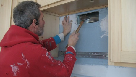
The Mitsubishi ceiling cassette requires a panel for circuitry access. After the unit was installed we framed out the area with 2x blocking leaving a little clearance to the electronics. Then we cut the drywall to land half-way over the blocking. After installing drywall 'L' bead and compounding I cut a piece of 1/2 in. MDF and screwed it in with trim screws. I left a gap of about 1/8 in. between the panel and the drywall bead/opening.
Then we painted the panel at the same time as the ceiling.
You can see the panel but it's not too obtrusive.
Perhaps someday Mitsubishi will design the cassette unit so the return/supply cover will be large enough to conceal the electronics area and avoid an access panel all together.
Thanks for responding regarding the access panel! Your solution is very helpful and I agree with your suggestion that this is something Mitsubishi should have a ready made solution for.